Because RFL™ and Hubbell® have a policy of continuous product improvement, we reserve the right to change designs and specifications without notice.
RFL 9785 RFL Electronics Inc.
July 26, 2007 16-10 (973) 334-3100
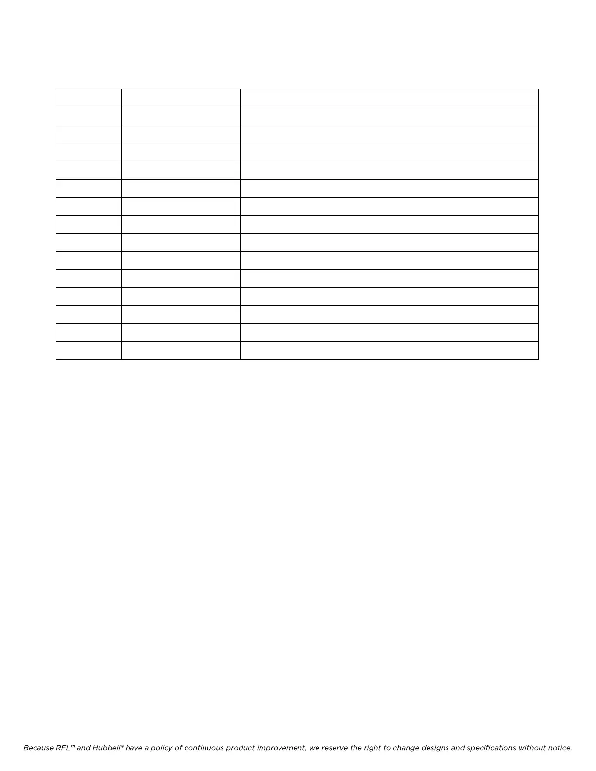
Table 16-2. Controls and indicators, RFL 9785 Checkback Module circuit board
Symbol Description, Marking Functional Description
J1 Connector header XILINX test connector
J4 Connector header For factory use only
J5 Jumper Selects normal or test modes
J6 Jumper Spare jumper
TP1 Test point Clock out signal
TP2 Test point Serial data out signal
TP3 Test point Test in progress signal
TP4 Test point Test out signal
TP5 Test point Checkback signal
TP6 Test point Checkback power level signal
TP7 Test point Signal ground
TP8 Test point Watchdog signal
TP9 Test point RS-232 transmit data signal
TP10 Test point RS-232 receive data signal