Because RFL™ and Hubbell® have a policy of continuous product improvement, we reserve the right to change designs and specifications without notice.
RFL
Decem
9785 RFL Electronics Inc.
ber 7, 2009 13-12 (973) 334-3100
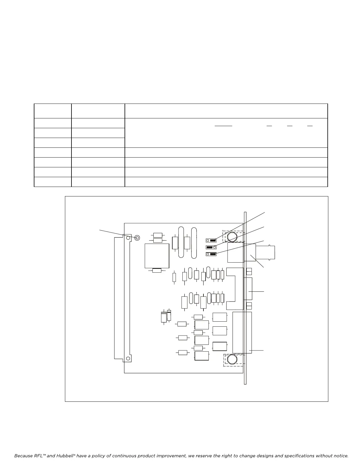
13.3.2 CONTROLS AND INDICATORS
Figure 13-6 shows the location of all jumpers, test points and connectors on the RFL 9785 SOE/IRIG-
B I/O module. The functions of these jumpers, test points and connectors are described in Table 13-4.
All of these items are accessible only when the module is removed from the chassis or is on a card
extender.
Table 13-3. Controls and indicators, RFL 9785 SOE/IRIG-B I/O module
Component
Designator
Name/Description Function
J1 Jumper INPUT J1 J2 J3
J2 Jumper Select TTL or bipolar inputs: Demodulated (TTL) OUT OUT OUT
J3 Jumper Modulated (bipolar) IN IN IN
J4 Connector IRIG-B input
P2 Connector RS-232 connection
TB1 Terminal Board Optional voice terminal board
TP1 Test Point Signal common
Figure 13-5. Controls and indicators for the RFL 9785 SOE/IRIG-B I/O module
TB
E
C
C
C
E5
E4
E3
E
J
J
R
R
R
R
CR
CR
CR
CR
CR
CR
C
C1
C1
C1
C1
C1
C1
C
C
C
T1
CR
C
C1
CR1
E1
J
J
P
R
TP
P
CR
CR
C1
C
OUT
OUT
OUT
I
I
I
6
9
5
1
.002uF
.002u
.001u
221
100
221
221
400CA
1.5KE
400CA
1.5KE
P6KE
16CA
16CA
P6KE
16CA
P6KE
P6KE
30CA
1K
.0068uF
.01u
.002u
.001u
.001u
XFM
P120
(95595
P6KE6.8
.001u
SB160
101691
101106
221
16CA
P6KE
30CA
P6KE
1K
.0068uF
.002u
TP 1
J3
J2
J1
J4
P2
TB 1
 Loading...