Because RFL™ and Hubbell® have a policy of continuous product improvement, we reserve the right to change designs and specifications without notice.
16.5 CONTROLS AND INDICATORS
Figure 16-7 shows the location of all controls and indicators on the Checkback module front panel.
Figure 16-8 shows the location of all controls and indicators on the Checkback module circuit board.
These controls and indicators are described in Tables 16-1 and 16-2. LEDs DS1 through DS9 and
switches SW1 through SW9 are accessible with the module installed in the chassis. All other controls
are accessible when the module is removed from the chassis or is on a card extender.
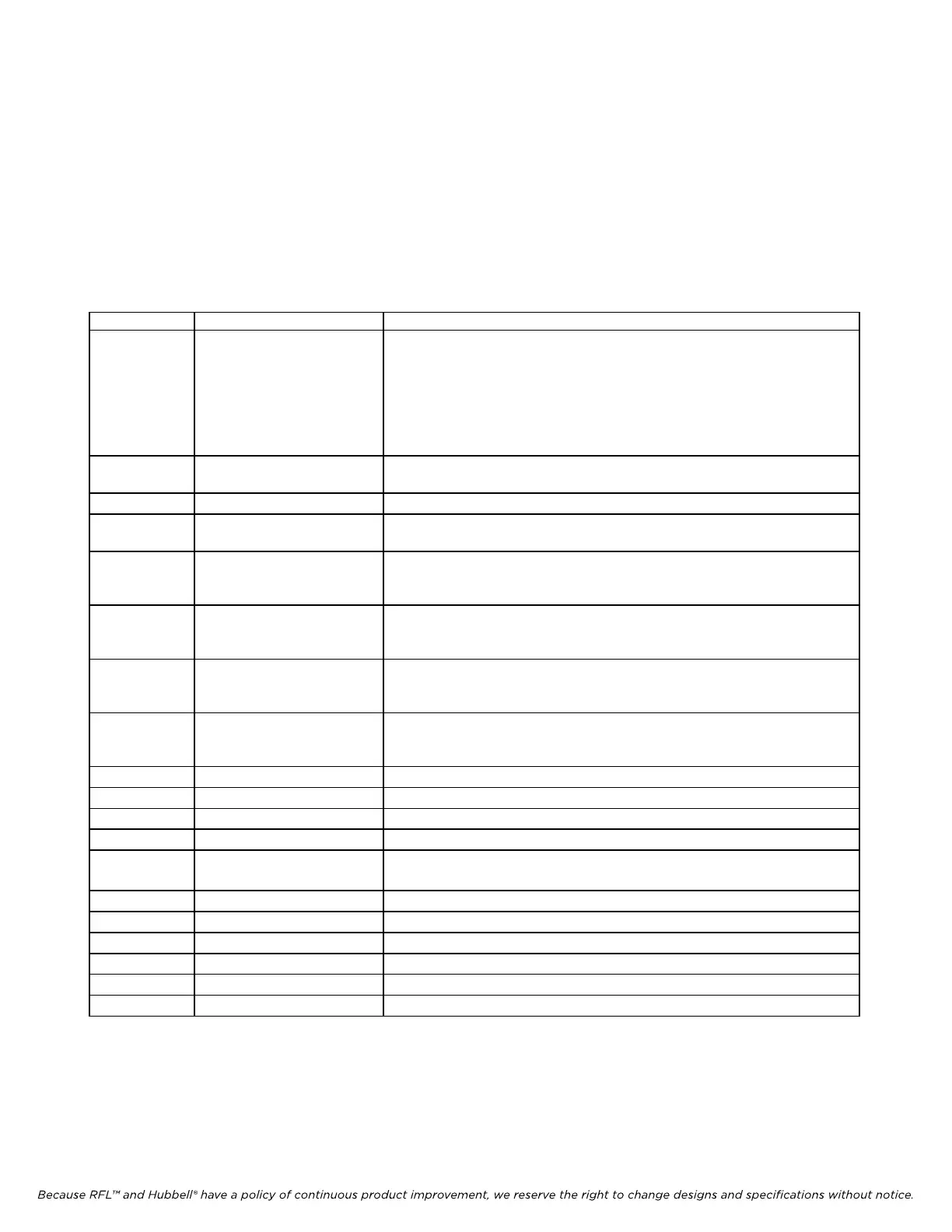
Table 16-1. Controls and indicators, RFL 9785 Checkback Module front panel
Symbol Description, Marking Functional Description
DIG1 to DIG3 Seven-segment displays Displays codes, numeric values, and “Err” error indications. “HC” will appear
when one of the Hard Carrier Request switches is pressed and a hard carrier is
being sent. “HCr” will appear when a hard carrier is being received. The
information displayed is controlled by DISPLAY SELECT switch SW1.
(See paragraph 16.6.1.1 for more information)
All display segments will light momentarily in turn when power is applied to the
module. This serves as a lamp test.
DS1 CODE RCVD indicator Lights when the seven-segment display is showing the code number being
received. Will flash when a valid code is received.
DS2 CODE SENT indicator Lights when the seven-segment display is showing the code being sent.
DS3 HOURS BETWEEN indicator Lights when the seven-segment display is showing the amount of time between
automatic checkback tests. Can only be displayed on Master checkback modules.
DS4 HOURS TO NEXT indicator Lights when the seven-segment display is showing the amount of time until the
next automatic checkback test. Can only be displayed on Master checkback
modules.
DS5 TEST RUN indicator Lights when the seven-segment display is showing the number of tests run since
the last time the test log was reset. Can only be displayed on Master checkback
modules.
DS6 TEST PASSED indicator Lights when the seven-segment display is showing the number of successful tests
run since the last time the test log was reset. Can only be displayed on Master
checkback modules.
DS7 TEST FAIL indicator Lights when the seven-segment display is showing the number of test failures
that have occurred since the last time the test log was reset. Can only be
displayed on Master checkback modules.
DS8 PASS indicator Lights if the system passed the last checkback test.
DS9 FAIL indicator Lights if the system failed the last checkback test.
SW1 DISPLAY SELECT switch Selects display mode. (See paragraph 16.6.1.1 for more information)
SW2 START TEST switch Manually starts checkback test. (Tests can only be initiated at the Master.)
SW3 RESET LOG switch Manually resets the test log. This sets the TESTS RUN, TESTS PASSED, and
TESTS FAILED totals to zero.
SW4 UP switch Increases value on display, one number, each time it is pressed.
SW5 DOWN switch Decreases value on display, one number, each time it is pressed.
SW6 HC1 switch Manually activates Hard Carrier 1 when pressed and held for five seconds.
SW7 HC2 switch Manually activates Hard Carrier 2 when pressed and held for five seconds.
SW8 HC3 switch Manually activates Hard Carrier 3 when pressed and held for five seconds.
SW9 HC4 switch Manually activates Hard Carrier 4 when pressed and held for five seconds.
RFL 9785 RFL Electronics Inc.
July 26, 2007
16-8 (973) 334-3100