Because RFL™ and Hubbell® have a policy of continuous product improvement, we reserve the right to change designs and specifications without notice.
4.8.2.3 Reflected Power
It is strongly recommended that the reflected power (SWR) on the installed line be verified. This is
most easily accomplished by using a PLC Test Set, such as the Signal Crafters Model 70. Following
the instructions for the test set and the tuning equipment, the line tuning unit should be adjusted to
obtain the lowest possible reflected power.
The RFL 9785 can be upgraded to automatically measure the amount of transmitted power reflected
back to the local receiver. The reflected power can be read locally or remotely using RFL Web
Commander or Hyper-terminal.
4.8.3 RECEIVER
After the transmitters at each end of the line have been setup, the receive portions of the 9785 must be
adjusted for the actual receive signal level. There is a coarse (attenuator) and fine (level) adjustment
for the receive level.
4.8.3.1 Input Attenuator
Adjust the input attenuator as follows:
1. Set the input attenuator (J1 on the Receiver Downshifter) to “50 dB”.
2. With the system in place and the far end transmitting a 10W block signal, measure the receive
level using a FSVM. The FSVM must be set to the frequency being transmitted by the far end .
The level should be measured at the receive test point TP20 (white), with the reference
common at TP1 (black) on the Receiver Downshifter.
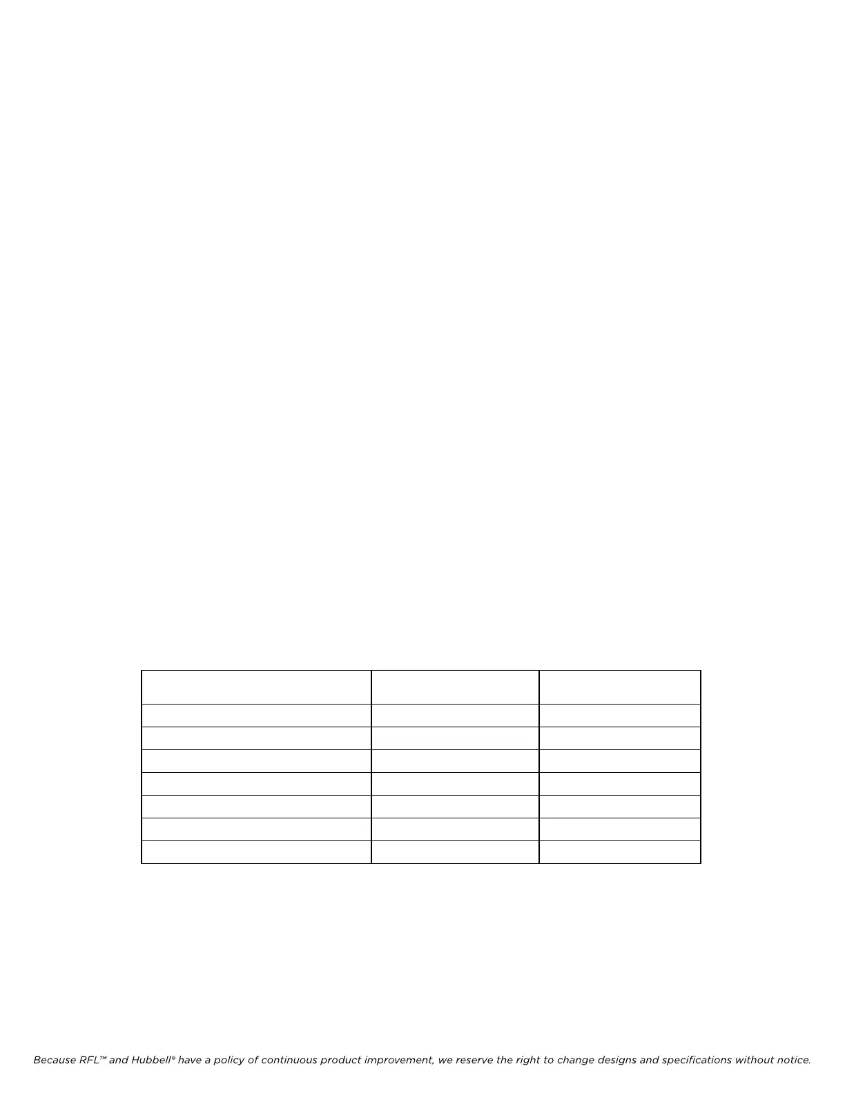
3. Using Table 4-3, determine the appropriate input attenuator setting (J1) and gain setting (J2)
and configure the Receiver Downshifter Module accordingly.
Table 4-3. Input Attenuator Settings
Measured
Receive Level
Jumper J1
(Attenuation)
Jumper J2
(Gain-Hi/Lo)
5 - 15 mVrms 0 dB HI
15 - 75 mVrms 0 dB LO
75 - 150 mVrms 10 dB LO
150 - 500 mVrms 20 dB LO
0.5 - 1.5 Vrms 30 dB LO
1.5 - 5 Vrms 40 dB LO
Above 5 Vrms 50 dB LO
4.8.3.2 Input Level Adjust
Adjust the GAIN potentiometer (R69) on the front of the Receiver Downshifter Module to achieve a
0 dB reading on the carrier level indicator.
RFL 9785 RFL
Electronics Inc.
March 24, 2008 4-14 (973) 334-3100