Because RFL™ and Hubbell® have a policy of continuous product improvement, we reserve the right to change designs and specifications without notice.
12.3 THEORY OF OPERATION
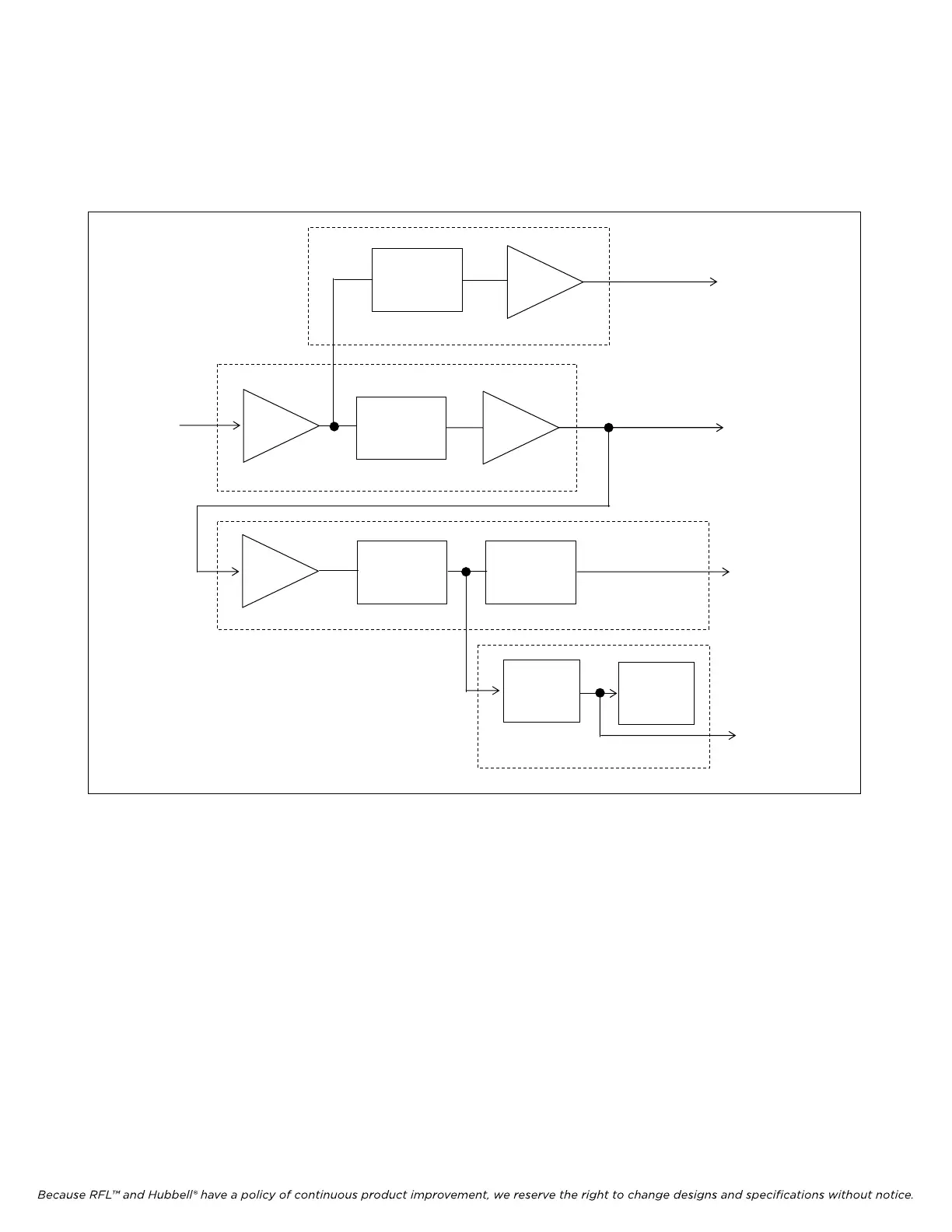
The RFL 9785 Receiver Detector module contains a narrowband filter, a signal monitoring circuit, a
carrier level indicator, and an optional voice filter. A block diagram of the Receiver Detector module
appears in Figure 12-2 and its schematic appears in Figure 12-5.
INPUT
BUFFER
VOICE
BANDPASS
FILTER
BUFFER 24 KHZ OUT
BUFFER
PRECISION
RECTIFIER
COMPARATOR
TO
AM
LOGIC
24 KHZ
FROM
RECEIVER
DOWNSHIFTER
MODULE
NARROWBAND
SIGNAL LEVEL MONITOR
METER
DRIVE
CIRCUIT
DIGITA
L
PANEL
TO
EXTERNAL
METER
(OPTIONAL)
CARRIER LEVEL INDICATOR
FILTER
BUFFER
OPTIONAL VOICE FILTER
VOICE OUTPUT
TO VOICE
MODULE
Figure 12-2. Block diagram, RFL 9785 Receiver Detector Module
12.3.1 NARROWBAND FILTER
The output signal from the Receiver Downshifter module (Section 10) enters the Receiver Detector
module at edge connector terminal C13. It is then applied to operational amplifier U7A, which serves
as an input buffer. From there, it passes to an active narrowband filter, formed from quad operational
amplifiers U8 and U9, and their associated components.
The output of the filter is buffered by operational amplifier U3A. FILT LEVEL potentiometer R90
varies the gain of U3A, which controls the amplitude of the 24KHZ OUT signal at edge connector
terminal A13.
There are three types of Receiver Detector modules. The 106515-6 has a 500Hz bandwidth (BW)
filter, the 106515-7 has a 1000Hz bandwidth (BW) filter and the 106515-8 has a 1500Hz bandwidth
(BW) filter.
RFL 9785 RFL Electronics Inc.
July 7, 2006 12-3 (973) 334-3100