Because RFL™ and Hubbell® have a policy of continuous product improvement, we reserve the right to change designs and specifications without notice.
U1
C8
P1
U2
DS1
J1
C3
C30
U6
U3
R23
J2
TP1
U4
RZ3
U5
SW6
CR
Z1
SW10
C1
1
C24
C6
C5
C4
C1
7
C1
4
C23
C2
2
C2
5
C3
2
C3
3
C1
2
R8
R1
R11
R12
R13
DS2
DS3
DS4
DS5
DS6
DS7
DS8
DS9
C2
C1
C1
5
C31
R18
TP2
TP3
TP5
TP4
TP6
C
R
4
2
RZ2
SW8SW9
SW7 SW5 SW4 SW3
CR
2
SW2 SW1
TP8
U7
R3
3
TP7
0
0KHZ
KHZ
X
X
X
X
X
X
XXX
1
1
+
+
+
+
+
+
+
+
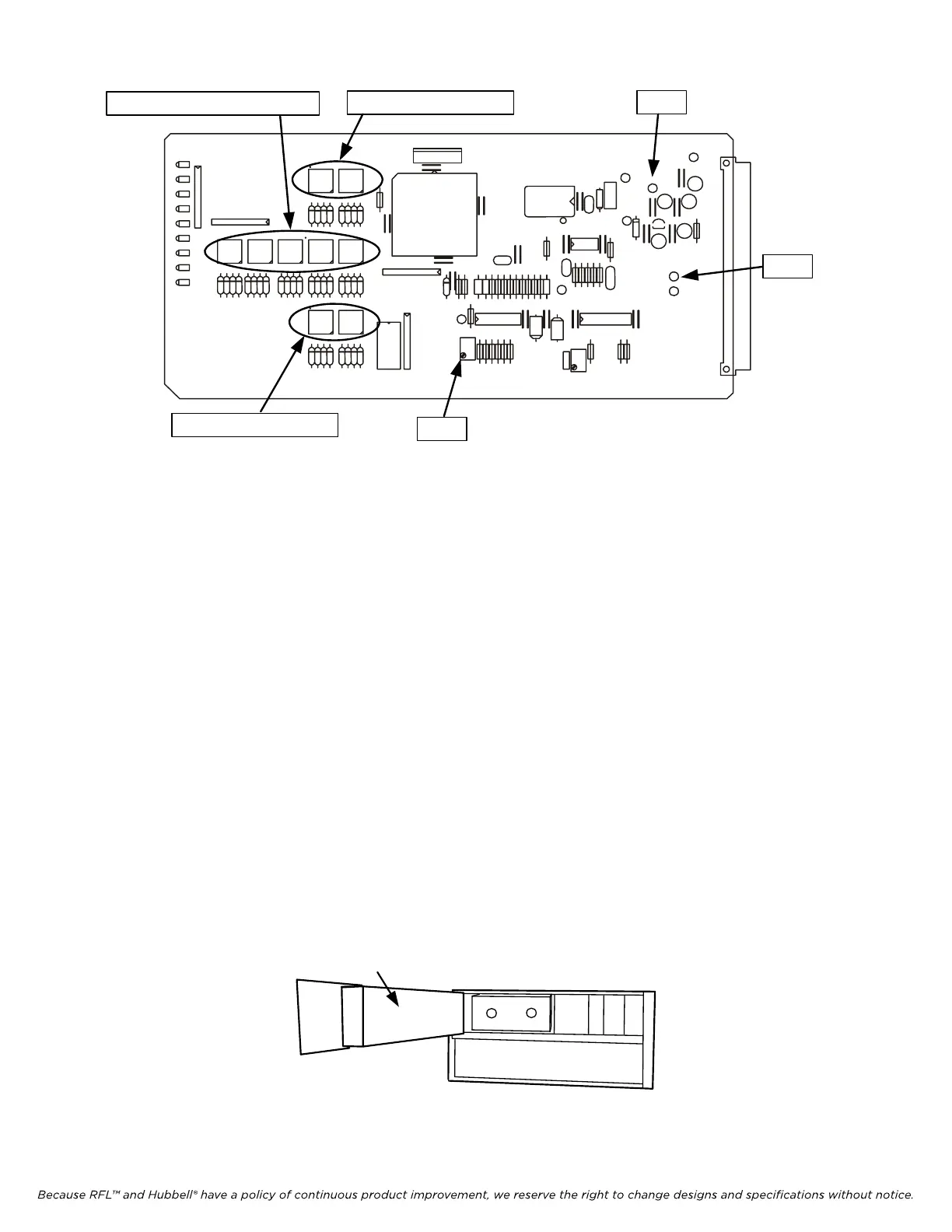
SW3 - SW7 Center Frequency
SW1 - SW2 Shift Down
R23
TP2 (-)
TP4 (+)
SW8 - SW9 Shift Up
Fi
gure 22-5. Controls and Indicators, RFL 9780/85 Transmitter Module (106505)
1. Power down.
2. Check the Transmitter module output level by placing the module on an Extender Card
(RFL P/N 9547-1870). Low power is keyed either with the reserve keying input or by setting
the AM Logic Board Switches SW1-3 and SW1-4 to OFF, and placing the toggle switch on the
AM Logic Board to the UP position.
a. Power up.
b. Connect an oscilloscope to TP4 (+) and TP2 (-).
c. Observe a 1.9V p-p undistorted waveform while transmitting low power 5 (10) watts. If
necessary, adjust R23 to attain the proper level. A 6V p-p undistorted sine wave should
be observed while transmitting high power 50(100) watts.
d. Power down and reinstall the transmitter module in the 9785 chassis.
e. Power up.
3. Open the front door on the 9508 RF Chassis 50 watt unit as shown below.
Location of 50W
Power Amp Module
Fi
gure 22-6. Location of 50W Power Amplifier
RFL 9785 RFL E
lectronics Inc.
March 1, 2013 22-5 (973) 334-3100