Because RFL™ and Hubbell® have a policy of continuous product improvement, we reserve the right to change designs and specifications without notice.
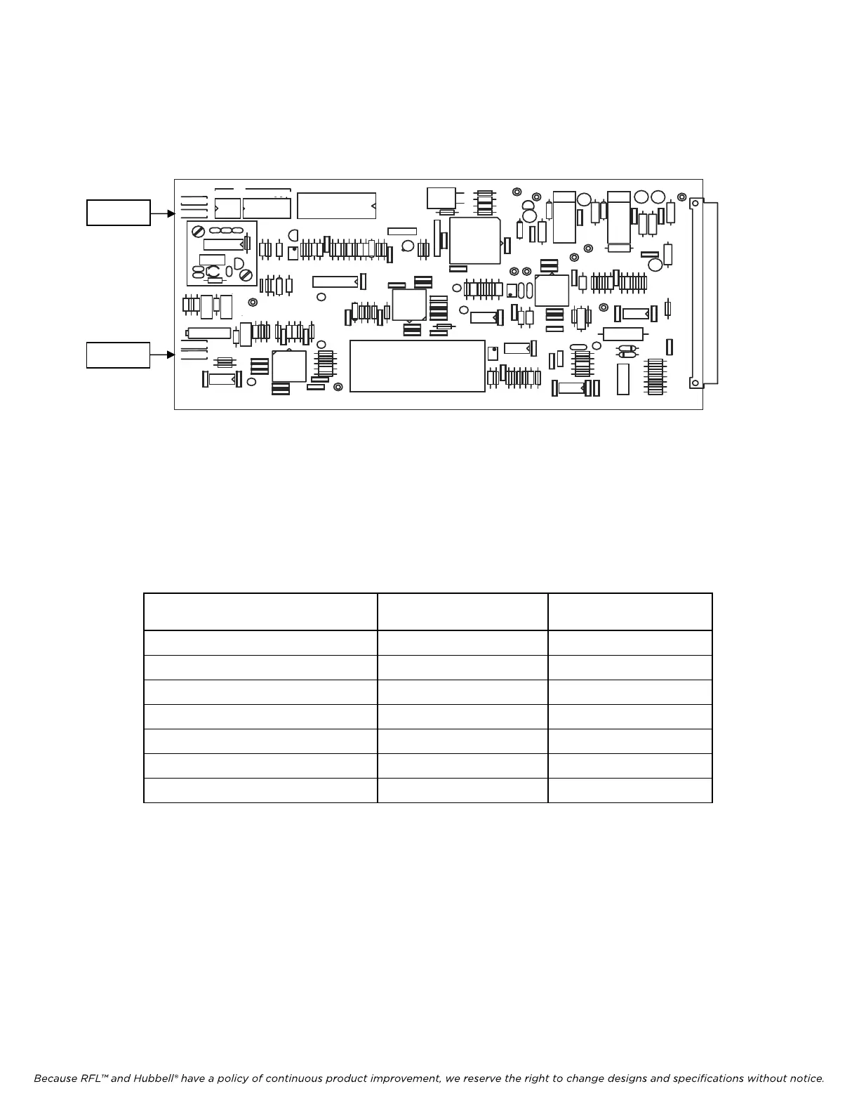
3) Key the remote transmitter ON, measure the incoming signal level on the RX Downshifter module
with a FSVM connected to TP20 (White - “+”) and TP1 (Black - “COM”).
C
R
R
C
R
C
C
C
R
R
C
C
R
L
C
C
C
C
C
R
R
R
R
R
R
R
R
R
R
R
R
R
R
R
R
R
R
R
R
R
R
R
R
R
R
R
R
R
R
R
R
RR
R R
R
L
L
L
C
C
C
C
C
C
C
C
C
C
C
C
C
C
C
C
C
C
C
C
C
L
C
C
C
C
C
C
C
C
C
C
C C
C
C
J
C
C
C
C
R
C
C
L
L
C
C
C
C
C
C
L
C
C
C
C
C
R
C
C
C
9785 RX DOWNSHIFTER ECB NO
G
I
1999 RFL ELECTRONICS INC.,
.2
1 3 6
1
2
5
+
+
+
+
+
+
+
+
+
.5W47.5
7.
5
5-
2
TP1 (COM)
TP20 (+)
hit
Figure 22-3. Controls and Indicators, RFL 9785 Receiver Downshifter Module (106575) - first
4) Set the attenuator and gain jumpers on the Rx Downshifter module as per Table 4.3.
Table 22-1 Input Attenuator Settings
Measured
Receive Level
Jumper J1
(Attenuation)
Jumper J2
(Gain-Hi/Lo)
5 - 15 mVrms 0 dB HI
15 - 75 mVrms 0 dB LO
75 - 150 mVrms 10 dB LO
150 - 500 mVrms 20 dB LO
0.5 - 1.5 Vrms 30 dB LO
1.5 - 5 Vrms 40 dB LO
Above 5 Vrms 50 dB LO
RFL 9785 RFL Electronics Inc.
March 1, 2013 22-2 (973) 334-3100