Because RFL™ and Hubbell® have a policy of continuous product improvement, we reserve the right to change designs and specifications without notice.
2) Key the remote transmitter ON and measure the receive signal level on the RX Downshifter module
with a FSVM set for the carrier frequency connected to white TP20 (White - “+”) and TP1 (Black –
“COM“).
3) On the Rx Downshifter module, set the Attenuator and Gain Jumpers as per table 4-3.
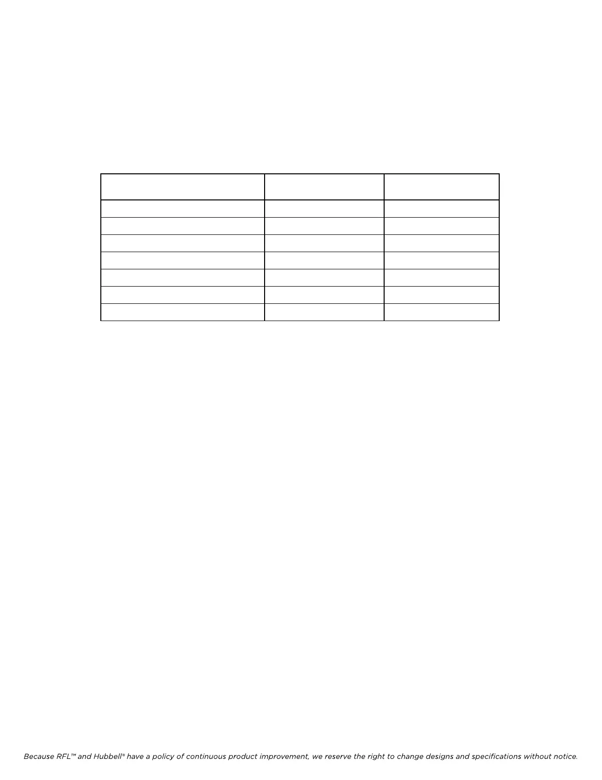
Table 22-7 Input Attenuator Setting
Measured
Receive Level
Jumper J1
(Attenuation)
Jumper J2
(Gain-Hi/Lo)
5 - 15 mVrms 0 dB HI
15 - 75 mVrms 0 dB LO
75 - 150 mVrms 10 dB LO
150 - 500 mVrms 20 dB LO
0.5 - 1.5 Vrms 30 dB LO
1.5 - 5 Vrms 40 dB LO
Above 5 Vrms 50 dB LO
4) On the Rx Downshifter module move the “+” lead of the FSVM set for carrier frequency to TP13
(Yellow – “+”).
5) On the Rx Downshifter module adjust R69 (“gain”) to obtain a reading of 200 mVrms.
6) Place the Rx Detector Module on an extender module.
a) Connect a multimeter to TP5 (Yellow – “+”) and TP1 (Black – “-“).
b) Adjust R90 to obtain a reading of 3.16 Vdc.
7) Adjust R34 on the Rx Detector module to obtain a reading of 0db on the Front Panel Meter.
8) Key the RESERVE input TB5-1 to TB5-2 on the rear SS I/O module and expect to obtain a level of
roughly –10dB on the Front Panel Meter.
9) Un-key remote transmitter.
c) Connect a multimeter to TP12 (+) and TP1 (Black – “-“) on the Rx Detector module.
d) Adjust R26 to obtain a reading of 0.56Vdc. Note: R26 sets the low level alarm to –15dB down
from normal level.
RFL 9785 RFL Electronics Inc.
March 1, 2013 22-14 (973) 334-3100