Because RFL™ and Hubbell® have a policy of continuous product improvement, we reserve the right to change designs and specifications without notice.
9.2.1 50W POWER AMPLIFIER
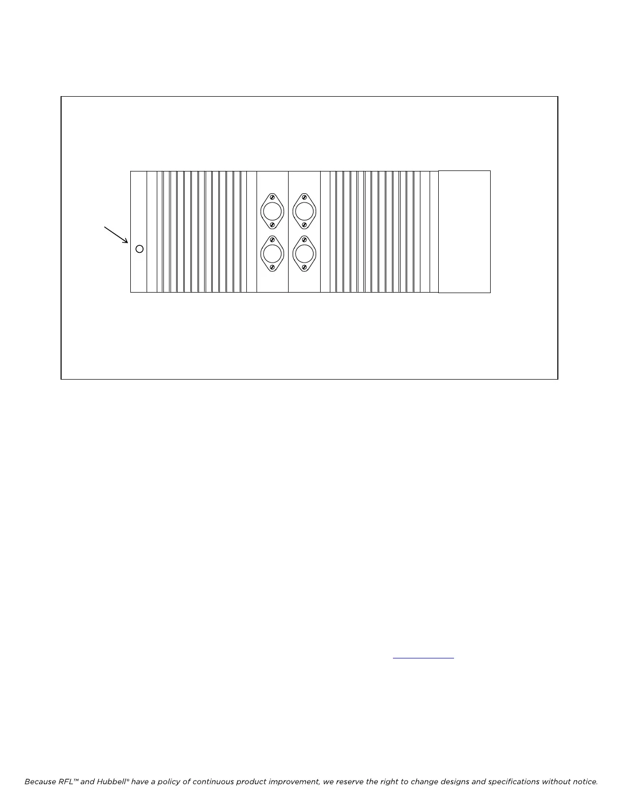
Green LED
Figure 9-4. RFL 9508 Power Amplifier
9.2.1.1 DESCRIPTION
The Power Amplifier is mounted on the front cover of the RFL 9508 RF Chassis. The function of the
Power Amplifier is to amplify the RF outputs of the RFL 9780/85 terminal before these signals are
passed to the line coupling equipment. The Power Amplifier develops an RF output of 50 Watts. A
green LED is located on the left side of the Power Amplifier front panel as shown in Figure 9-4. The
LED is ON when the power amplifier is transmitting.
In those applications that require 100 Watts of RF output, two 50 Watt Power Amplifiers are
connected in parallel. The second 50 Watt Power Amplifier is mounted in a 3U chassis directly above
the RFL 9508 chassis as shown in Figure 9-1. There must be a 1U minimum space between these
chassis for convection cooling. This additional 3U chassis will contain a total of five modules as
follows: a Power Amplifier, a Power Amplifier Power Supply, a Mother Board, a Tx Filter and an
External Amp Connector Board, as shown in Figure 9-17.
For commissioning using the 50W and 100W Power Amplifiers see Section 22.2
RFL 9785 RFL Electronics Inc.
May 16, 2011 9-5 (973) 334-3100