Because RFL™ and Hubbell® have a policy of continuous product improvement, we reserve the right to change designs and specifications without notice.
2) Check the Transmitter module output level by placing the module on an Extender Card (RFL P/N
9547-1870).
a) Connect an oscilloscope to TP4 (+) and TP2 (-).
b) Observe 6V p-p undistorted waveform while transmitting 10 watts. If necessary, adjust R23 to
attain proper level.
3) Check the carrier output level by removing the coax from carrier output to the line tuner.
a) Connect a 50-ohm non-inductive dummy load of sufficient wattage to the carrier output
connector.
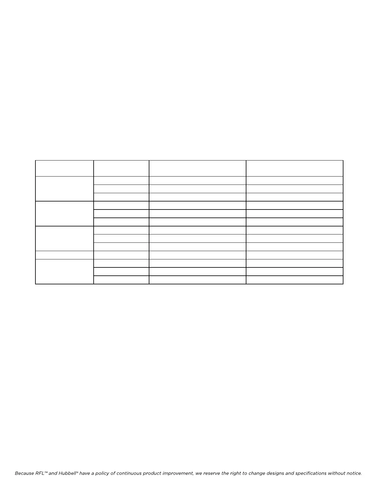
4) Verify proper frequency jumper positions, J1-J7, on the 9785 Output Filter Modules as per Table
9.2.
Table 22-4 RFL 9785 Output Filter Modules, frequency range
Filter Module
Part No.
Jumper Position Passband Frequency Range Approximate Frequency Of
Greatest Attenuation
106530-1, -11 A 30 to 41.5 kHz 90 kHz
B 38 to 52.5 kHz 114 kHz
C 49 to 67.5 kHz 147 kHz
106530-2, -12 A 64 to 88.5 kHz 192 kHz
B 85 to 117.5 kHz 255 kHz
C 114 to 157.5 kHz 342 kHz
106530-3, -13 A 154 to 212.5 kHz 462 kHz
B 209 to 288.5 kHz 627 kHz
C 285 to 393.5 kHz 855 kHz
106530-4, -14 . . . 390 to 537.5 kHz 1170 kHz
106530-5, -15 A 114 to 157.5 kHz 342 kHz
B 154 to 212.5 kHz 462 kHz
C 209 to 288.5 kHz 627 kHz
5) Place the Frequency Selective Volt Meter (FSVM) leads on the Output Filter Module TP1 (Brown
– “COM”) and TP3 (White – “IN”). See Step (Section 22. of Simplified Commissioning
Procedure for 9785 Output Filter Module diagram.
NOTE: For proper filter operation, all seven jumpers (J1 through J7) on each Filter
Module must be placed in the same block (all in A, all in B, or all in C).
6) Adjust R2 on the Power Amplifier Module located on the rear of the chassis to obtain a reading of
22.36 Vrm
s (40dbm) while transmitting 10 watts.
RFL 9785 RFL Electronics Inc.
March 1, 2013 22-10 (973) 334-3100