Because RFL™ and Hubbell® have a policy of continuous product improvement, we reserve the right to change designs and specifications without notice.
18.3.2 CONTROLS AND INDICATORS FOR 106455-3 & -4 P.S. I/Os
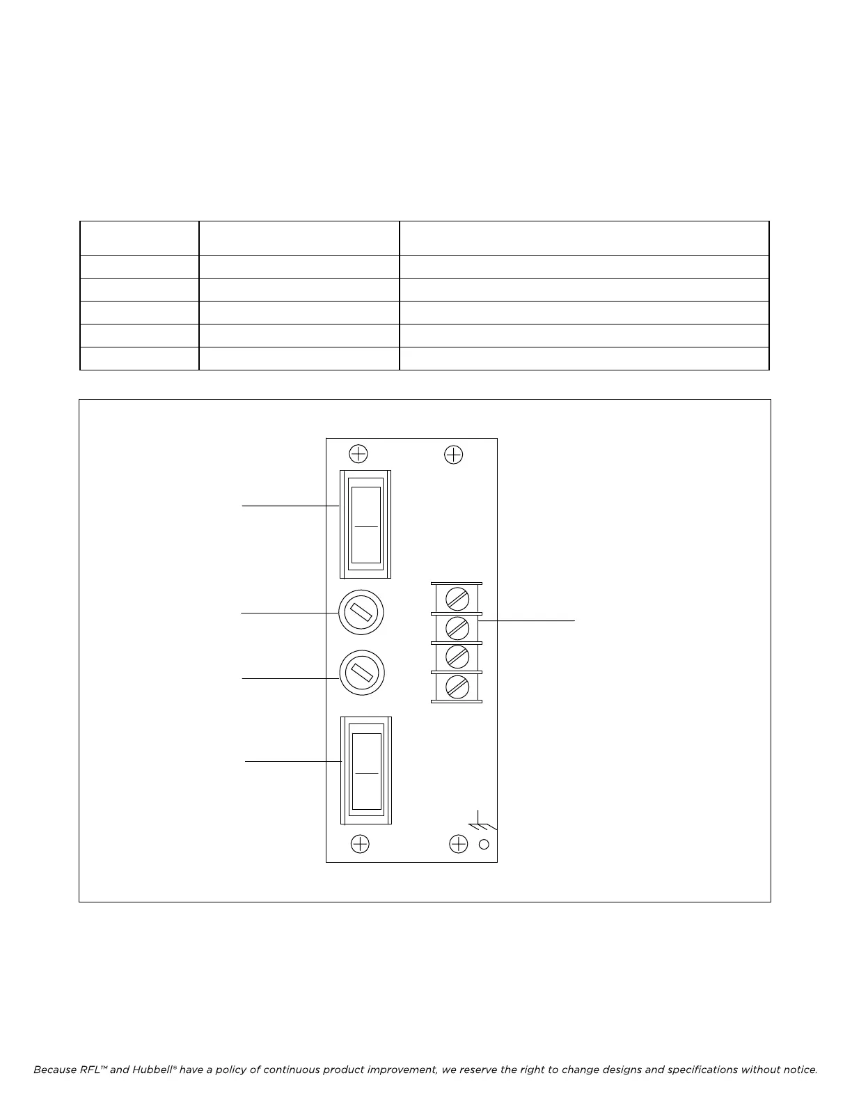
Figure 18-8 shows the location of all controls on the RFL 9785 Dual Power supply I/O module. These
controls are described in Table 18-5.
Table 18-5. Controls and indicators, RFL 9785 Dual Power Supply I/O module
Component
Designator
Name/
Description
Function
F1 Fuse Fuse for power supply No. 1
F2 Fuse Fuse for power supply No. 2
SW1 Switch ON/OFF switch for power supply No. 1
SW2 Switch ON/OFF switch for power supply No. 2
TB1 Terminal Board Input power connections
1
0
P.S. - A
ON
P.S.I/O
OFF A
F1 SB+
4A SB-
SB+
F2 SB-
B
ON
OFF
P.S. - B
1
0
SW1
F1
F2
SW2
TB1
Figure 18-8. Controls and indicators, RFL 9785 Dual Power Supply I/O module
RFL 9785 RFL
E
lectronics Inc.
June 18, 2009
18-17 (973) 334-3100