Because RFL™ and Hubbell® have a policy of continuous product improvement, we reserve the right to change designs and specifications without notice.
6.4.1 BLOCK HOLD TIMER APPLICATION
A “Block Hold Timer” can be set between 4ms and 28ms in increments of 4ms. Dip Switches SW2-6
thru SW2-8 are used to set the Block Hold Time for this application. This setting will ONLY affect
the Block Output generated as a result of received signal detection.
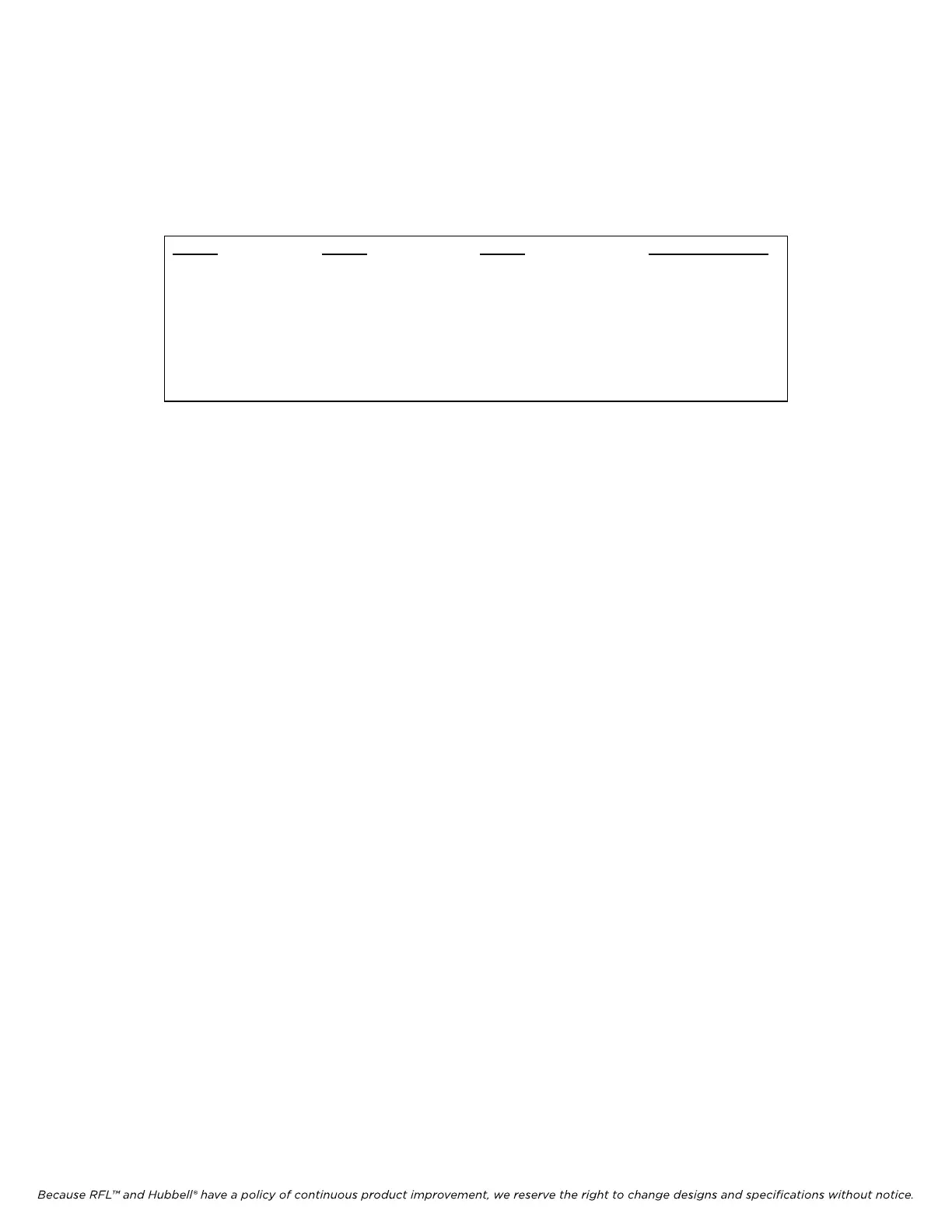
Table 6-5. Switch Settings – Block Hold Timer, DIP Switch SW2-6, -7, -8
SW2-6
OFF(DOWN)
OFF(DOWN)
OFF(DOWN)
OFF(DOWN)
ON(UP)
ON(UP)
ON(UP)
ON(UP)
SW2-7
OFF(DOWN)
OFF(DOWN)
ON(UP)
ON(UP)
OFF(DOWN)
OFF(DOWN)
ON(UP)
ON(UP)
SW2-8
OFF(DOWN)
ON(UP)
OFF(DOWN)
ON(UP)
OFF(DOWN)
ON(UP
OFF(DOWN)
ON(UP)
Block Hold Timer
0ms (Default Setting)
4ms
8ms
12ms
16ms
20ms
24ms
28ms
Application Notes:
• When using the 9785 Checkback feature the Block Hold Timer MUST be set for 0ms. The
Checkback data-bits track the Block Output. As such, they are also extended by the same
amount as defined by the Block Hold Timer. This will adversely affect the Checkback
Communications since the “low” and “high” bit periods would not be uniform.
• For Two-Wire applications (SW2-1 = OFF): The local Block Output will also be extended by
the time specified by the Block Hold Timer setting whenever the Local Carrier is keyed.
For Four-Wire applications (SW2-1 = ON): The Block Hold Timer does not affect the Local
Block Output when the Local carrier is keyed. However, a fixed 3ms hold-timer is used to
extend the Block Output.
RFL 9785 RFL
Electronics Inc.
February 7, 2007 6-8 (973) 334-3100