Because RFL™ and Hubbell® have a policy of continuous product improvement, we reserve the right to change designs and specifications without notice.
RFL Electronics Inc.
March 2005
RFL 9785
Input Ratings
48 Volt Inputs
Will not operate at or below: 28 V
olts
Will operate at or above: 35 Volts
Minimum pulse duration: 100 µSec
Input current: <10mA, 5mA typical
125 Volt Inputs
Will not operate at or below: 70 V
olts
Will operate at or above: 90 Volts
Minimum pulse duration: 100 µSec
Input current: <10mA, 5mA typical
250 Volt Inputs
Will not operate at or below: 140 Volts
Will operate at or above: 175 Volts
Minimum pulse duration: 100 µSec
Input current: <10mA, 5mA typical
Note: Logic level (5 volt nominal ) outputs are available.
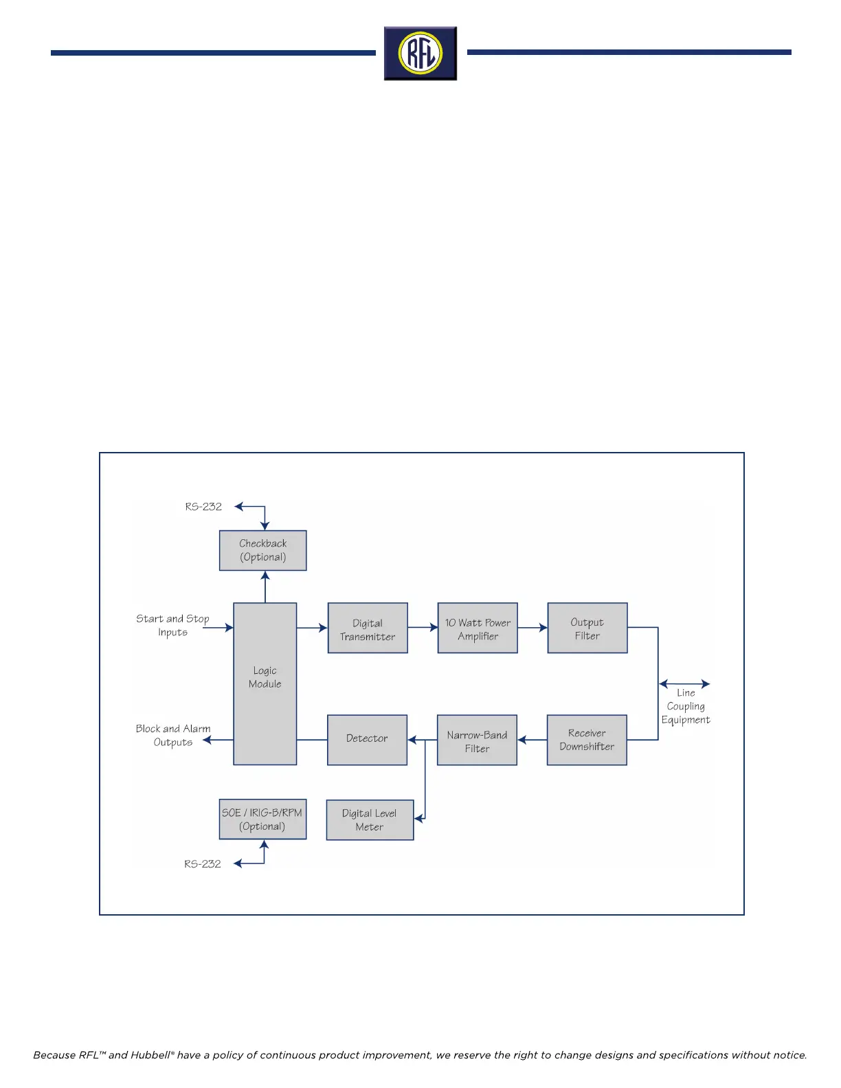
Figure 1. Typical RFL 9785 Programmable ON/OFF Powerline Carrier System Block Diagram.
Two Wire Operation
The RF transmitter output and receiver input are jumpered
together with two UHF connectors, J5 and J7. Either con-
nector can be connected to the line tuning equipment. This
provides a maximum continuous output power of 10 Watts
with a nominal input/output impedance of 50 Ohms.
Four Wire Operation
The RF transmitter output and receiver input are isolated
utilizing separate UHF connectors. The transmitter out-
put, J5, provides a maximum continuous output power of
10 Watts with a nominal output impedance of 50 Ohms.
In four wire operation the receiver input signal is connected
to J7. The receiver input impedance is jumper selectable
between a 50 Ohm termination mode and a high imped-
ance (>30 KΩ) non-terminated mode. The 50 Ohm termi-
nation mode has a maximum continuous power dissipa-
tion of 1 Watt.
Specifications subject to change without notice.
4