Because RFL™ and Hubbell® have a policy of continuous product improvement, we reserve the right to change designs and specifications without notice.
48/125DC
106535-1
PS I/O
+
+
-
-
Station
Battery Input
{
Switched
Station
Battery
Output
{
106455-1
TB10-1
TB10-2
TB10-3
TB10-4
TB4-1
TB4-2
TB4-3
TB4-4
+
+
-
-
ISO
Input
ISO
Input
{
{
Key
Start
Key
Stop
Part of 9785
SS I/O
TB7-1
TB7-2
TB7-3
TB7-4
TB7-5
TB7-6
Power
Fail
TX Fail
+5V
+15V
-15V
+12V
COM
Alarm Relay I/O
106465
Trans PWR Amp
Output
106505
106460
106530-X
Protector
9785 RF Line I/O
FSVM
TP3 H WHT
TP1 L BRN
Verify 7.07 Vrms ± 15mV (at 1W)
Verify 22.36 Vrms ± 45mV (at 10W)
Key 10W
Oscope
TP4 H
TP2 L
Verify at 10W = 6V P-P
Verify at 1W = 1.9V P-P
TX/Power Fail
TB5-1
TB5-2
+
-
ISO
Input
{
Key
Reserve
TX Fail
Output
Reserve
Sig. Input
AM Logic
Front
Door
LEDs
Start Key
Stop Key
Res Key
RMT Int (Ch Bk)
TX On
TX Fail
Part of
AM Logic
Start
Input
Stop
Input
106540
Verify
Power Fail LED
Start Key
Stop Key
Reserve Key
TX Out
J14
J10
W6
TB9-1
TB9-2
J5
TX Out
All relay contacts shown in the unenergized position
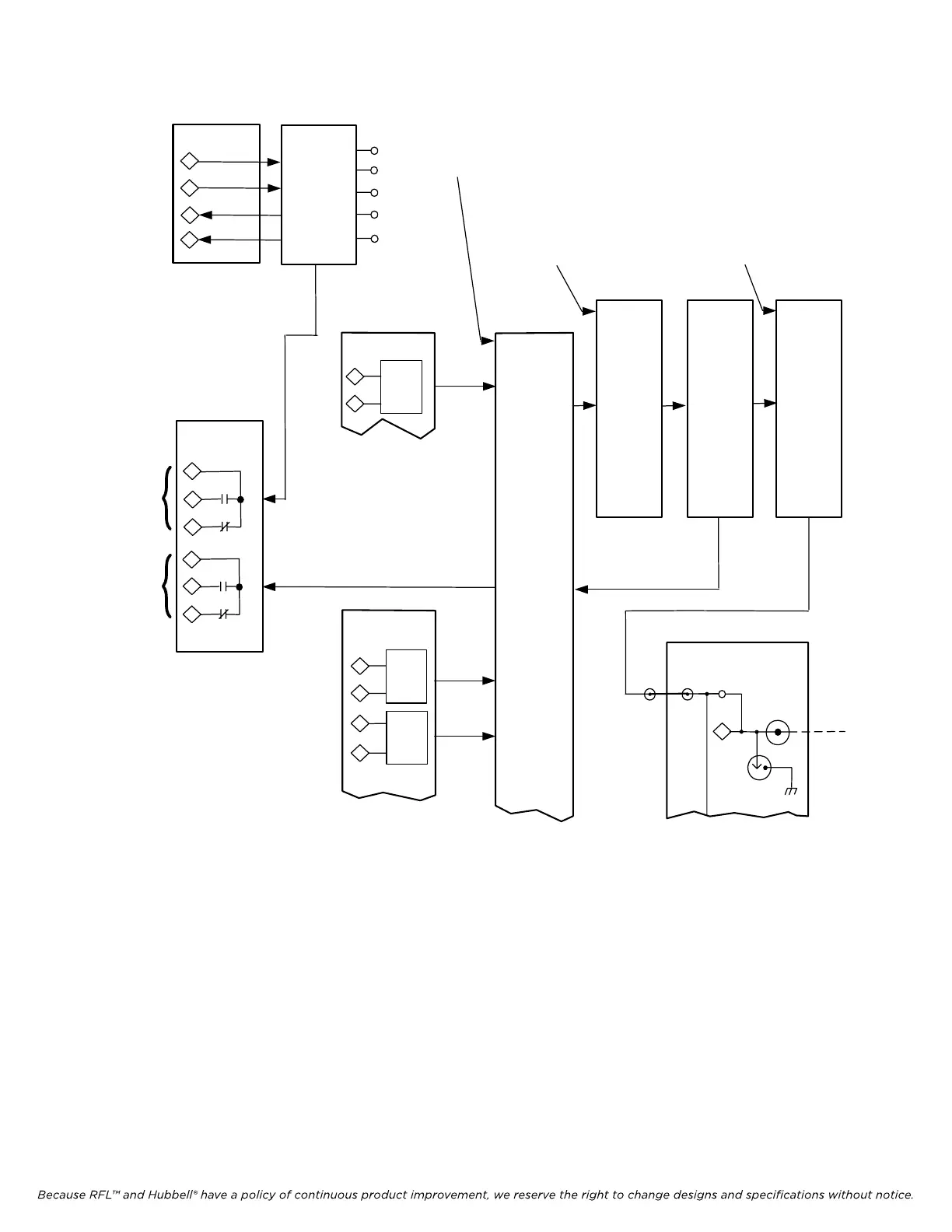
Figure 22-14. Block Diagram for Troubleshooting Part 1 of 2
RFL 9785 RFL Electronics Inc.
March 1, 2013 22-16 (973) 334-3100
 Loading...