Auxiliary Control Panels
An auxiliary control panel provides an extra row of
source buttons that can be assigned to an aux bus. This
single row of buttons can be used to select sources on
the aux output, or to visually follow what is selected on
an aux bus.
The switcher supports the V-053B, the V-159 series, and
AP-AUX2RU series of auxiliary control panels.
Auxiliary Control Panel Operation
The Auxiliary Control Panel can be assigned to either an
internal panel row, or an external panel row, depending
on the functionality you want. Only Auxiliary Control
Panels assigned to internal panel rows can be used for
menu auto follows, double press actions, or recording
custom controls.
In addition to source buttons, all Auxiliary Control Panels
include dedicated Aux Bank and Aux Bus buttons, as
well as control buttons.
• Source Buttons — allow you to select a video source
on the selected bus. If the Auxiliary Control Panel is
in Aux Bus mode, the source buttons select the video
source being fed out of the aux bus.
• Aux Bank and Bus Buttons — allow you to select
the specic Aux Bus that you want to assign the
Auxiliary Control Panel to.
• Source Buttons — allow you to switch between the
operating modes, and perform various operations
when in each mode.
BANK
1
BANK
2
BANK
3
BANK
4
BANK
5
BANK
6
AUX
1
AUX
2
AUX
3
AUX
4
AUX
5
AUX
6
AUX
7
AUX
8
Control Buttons Aux Bank/Bus Buttons
Source Buttons
Figure 26: Auxiliary Control Panel (24-Button)
The Auxiliary Control Panel allows you to select the
video source that is being fed out of any Aux Buses on
the switcher. You can select the Aux Bank and Aux Bus,
and the video signal you want
Tip: (Auxiliary Control Panels assigned to and internal panel
row only) If the Aux Bus you are selecting is set up as an AuxKey,
you can double-press the source button on the Auxiliary Control
Panel to assign the AuxKey to a row on the control panel. The
particular panel row that the AuxKey is assigned to is the panel
row that the Auxiliary Control Panel is assigned to from the Panel
Modules menu.
The control buttons on the Auxiliary Control Panel are
assigned as custom control shot box buttons, allowing
you to access the rst 14 custom controls from the shot
box pages. Shot Box Pages are assigned to the Auxiliary
Control Panel in the same way as they are assigned to a
Custom Control Shot Box Module.
BANK
1
BANK
2
BANK
3
BANK
4
BANK
5
BANK
6
AUX
1
AUX
2
AUX
3
AUX
4
AUX
5
AUX
6
AUX
7
AUX
8
CUST
OM01
CUST
OM02
CUST
OM03
CUST
OM04
CUST
OM05
CUST
OM06
CUST
OM07
CUST
OM08
CUST
OM09
CUST
OM10
CUST
OM11
CUST
OM12
CUST
OM13
CUST
OM14
Figure 27: Auxiliary Control Panel with Custom Control Shot
Box
1RU Remote Aux Panel Operation
The 1RU Remote Aux Panels provide remote control, or
monitoring, capability over one, or more, of the Aux
Buses on the switcher. These panels are typically located
close to the destination device that they route their
sources to. Video does not ow through these panels,
instead, the 1RU Remote Aux Panel interfaces with the
switcher to control the outputs of the Aux Bus.
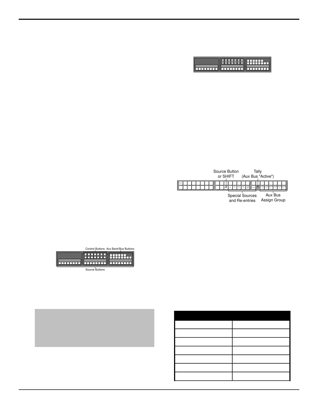
In addition to crosspoint buttons, all 1RU Remote Aux
Panels include dedicated buttons for Program, MEs, and
Clean Feed.
BLCK
MLE
1
MLE
2
MLE
3
CLEAN
FEED
PGM
ASSIGN
+4
ASSIGN
+8
ASSIGN
1
ASSIGN
2
ASSIGN
3
ASSIGN
4
SHIFT PV
Special Sources
and Re-entries
Aux Bus
Assign Group
Tally
(Aux Bus "Active")
Source Button
or SHIFT
Figure 28: 1RU Remote Aux Panel
All 1RU Remote Aux Panels include an on-air Tally LED
that indicates, when lit, that the Aux Bus controls a video
signal that is part of the program output.
Source selection on the 1RU Remote Aux Panel is the
same as selecting sources on a control panel row. The
sources that are assigned to the source buttons depend
on the Bus Map that has been assigned to the Aux Bus
the 1RU Remote Aux Panel is controlling. The 1RU
Remote Aux Panel can be assigned to any of either the
rst 10 or 12 Aux buses on the switcher. The Remote
Aux Panel can be assigned to the rst 12. To assign the
1RU Remote Aux Panel to a particular Aux bus, you
must use the assign buttons on the 1RU Remote Aux
Panel. These buttons are used in conjunction with each
other to select a particular Aux bus.
1RU Remote Aux PanelAux Bus to Control
Assign 1Bank 1: Aux 1
Assign 2Bank 1: Aux 2
Assign 3Bank 1: Aux 3
Assign 4Bank 1: Aux 4
Assign +4 and Assign 1Bank 1: Aux 5
Assign +4 and Assign 2Bank 1: Aux 6
Assign +4 and Assign 3Bank 1: Aux 7
Acuity Operation Manual (v9.2) — Auxiliary Control Panels • 105