FunctionButton
Allows you to have the keys from one
memory slew into the keys from the one
you are recalling.
EFF DISS
Allows you to use the keypad to enter the
number of the memory register where you
want to store a memory.
STORE
Allows you to set a new effects dissolve
rate for the ME.
EFF RATE
Allows you to set a new background
transition rate for the ME.
ME RATE
Allows you to set a new keyers transition
rate for the ME.
KEY RATE
Allows you to select the bank that you
want to store, or recall, a memory register
to.
BANK
Menu Keypad Module
This module is used to interact with the lower menu on
the touchscreen. The buttons along the bottom of the
module correspond to the buttons on the bottom of the
menu and the knobs correspond to the three knobs on
the menu.
HOME
UP
ONE
HOLD
TOP
MENU
MENU KEYPAD
Refer to Menu Keypad Module on page 26 for
information on using this module.
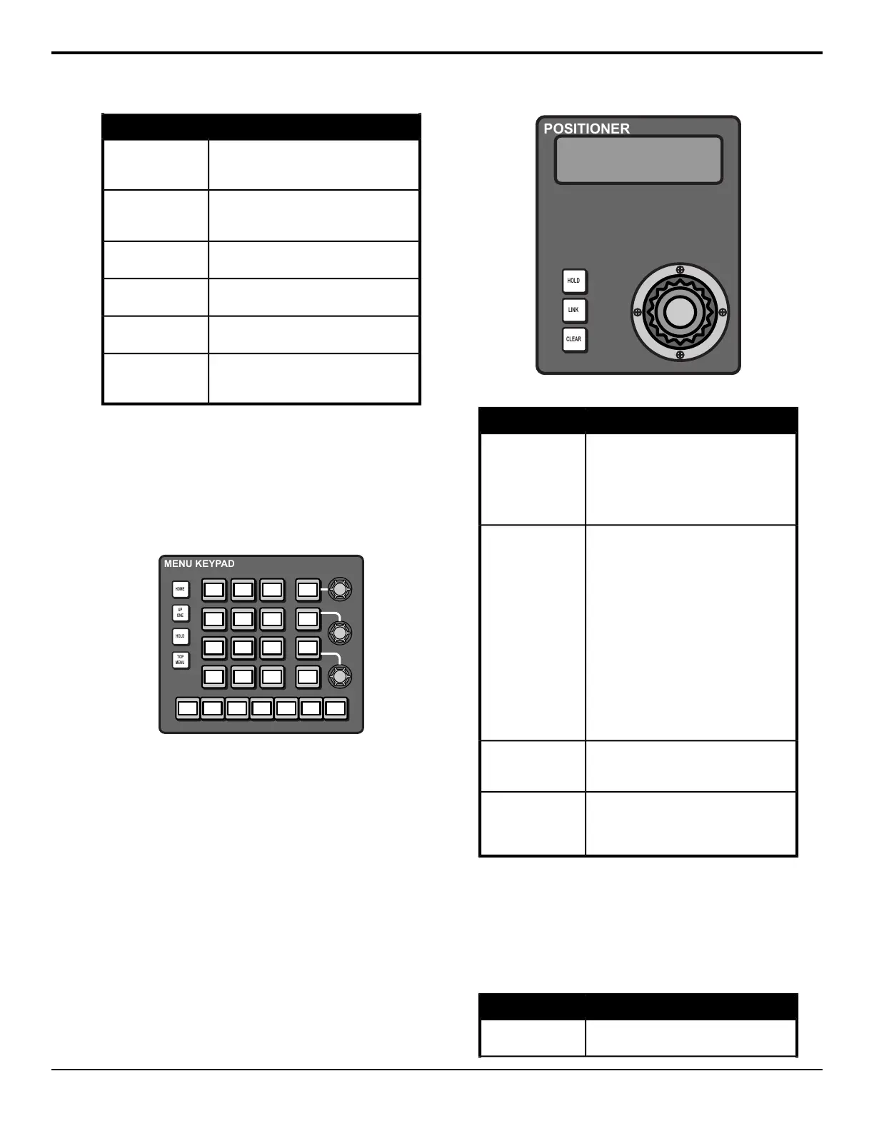
Positioner Module
This module supports the positioner that is used to
manipulate the position of wipes, patterns, ying keys,
and other menu knob values marked with arrows.
Table 5: Positioner Module Button Functions
FunctionButton
Allows you to lock the positioner module
to the element that it is currently
controlling. When locked (held), the button
is lit, and the positioner module does not
act on the normal auto-follow commands,
such as when you select a robotic camera.
HOLD
Allows you to add and remove elements
that are being controlled by the positioner
module. To add an element, press and
hold the LINK button, and then press the
SEL or crosspoint button for the element
you want to add. The LINK button lights
if more than one element is being
controlled by the positioner. If you select
another element that the positioner would
auto-follow, the current link settings are
lost. An example of linking would be to
link two flying keys together from separate
keyers. Double-press the LINK button
show all the items that are linked to the
positioner.
LINK
Allows you to center the position and
location of a flying key, or what is selected
on a keyer, ME, or aux bus.
CLEAR
The button on top of the positioner allows
you to cycle through what the positioner
is controlling. What menu items are cycled
through depends on the menu you are in.
Positioner Button
Preview
This module is used to select whether you are viewing
program or preview of a selected ME on the Preview
output.
Table 6: Preview Button Functions
FunctionButton
Allows you to select the ME to assign to
the preview output.
ME X
16 • Acuity
®
Control Panel Overview — Acuity Operation Manual (v9.2)