Carbonite Black Control
Panel Overview
The Acuity
®
frame can be controlled by the Carbonite
Black control panel using a Menu Display. The Menu
Display connects to the frame over ethernet the same
way an Acuity Rack Panel does. You can then connect
the Menu Display to the Carbonite Black control panel.
Tip: An ARP can be used instead of the Menu Display.
Control Panel Modules
Each Carbonite Black control panel is made up of a
number of distinct areas that control different aspects of
the switcher. Some of these areas may vary in size or
function, depending on the control panel you have.
KEY/ AUX/CUS T OM CONT R OL
PROGRAM
PRESET
KEY
PV
SHOW
ALPHA
SEL
CC
SEL
BKGD KEY 1 KEY 2 KEY3 KEY 4
DISS WIPE DVE MEDIA
TRANSITION 3
ROLL
CLIP
CUT
AUTO
TRANS
KEY 4
CUT
KEY 3
CUT
KEY 2
CUT
KEY 1
CUT
KEY 4
AUT O
KEY 3
AUT O
KEY 2
AUT O
KEY 1
AUT O
PUSH PUSH PUSH
HOME
TOP
MENU
UP
ONE
BANK
ENTER
HOLD
AUTO
SELECT
SELF
KEY
PST
PATT
2D
DVE
CHROMA
KEY
3D
DVE
KEY
MEM
BORDER
CHNL
MGMT
KEY
INV
MASK
MATTE
FILL
RECALL
STORE
FUNC
USB
1
2
7
6
8
9
11
10
4
5
3
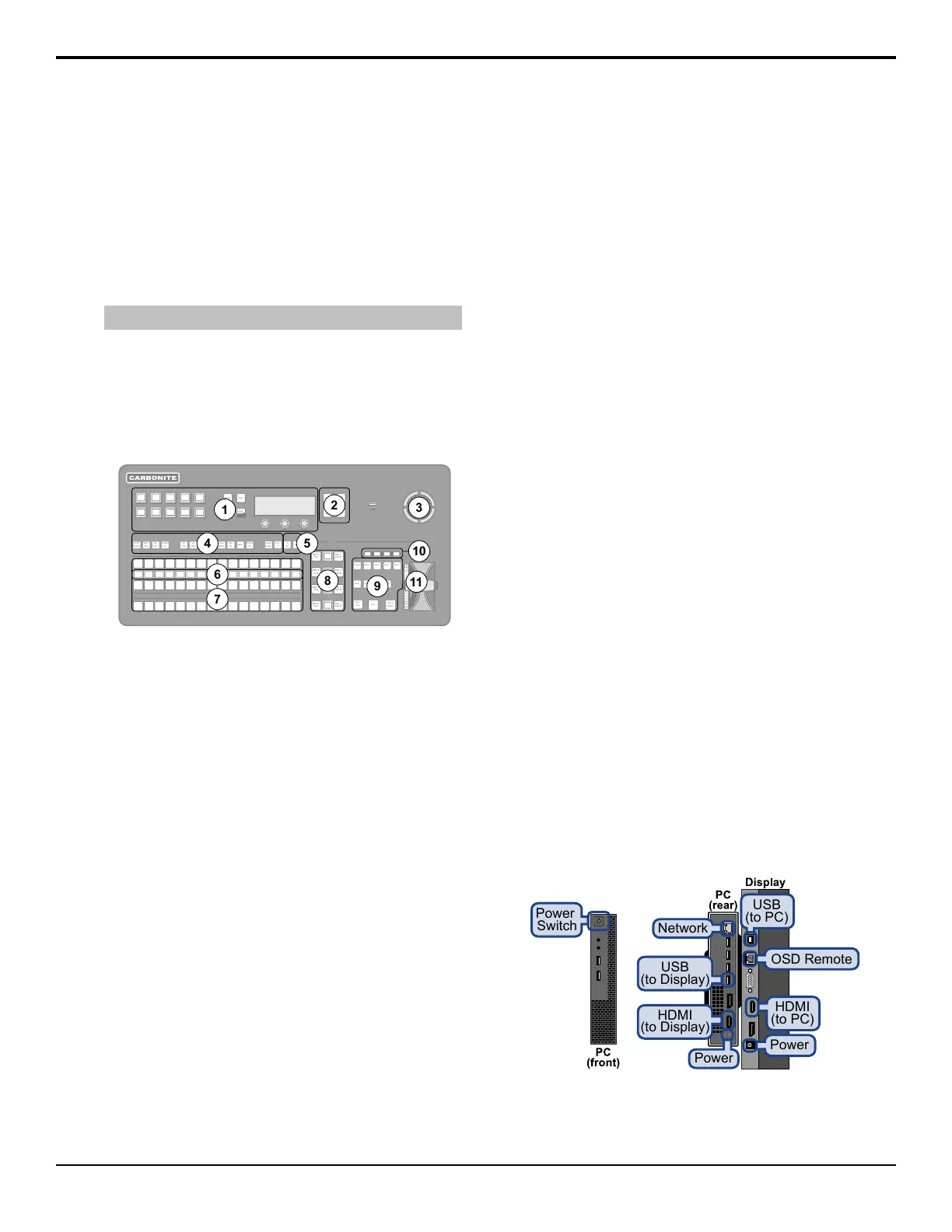
Figure 1: CB1 Control Panel
1. Memory — These buttons are used to store or recall
memories to one or more MEs at the same time.
Press and hold the STORE or RECALL button and
use the mnemonic buttons to select the MEs that you
want to store or recall to.
2. Menu Navigation Buttons — These buttons are
used to access switcher menus and move back and
forth between menus.
3. Positioner — The positioner is used to position and
size keys in the DVE, control some wipe, border,
and wash parameters, as well as control some
external devices.
4. Keyer Buttons — These buttons are used to choose
the type of key you want to use and apply modiers
to that key.
5. Select Buttons — These buttons are used to assign
the panel row to a custom control or a ME, key, or
aux.
6. Mnemonic Displays — The mnemonic display
shows the name of the source, or custom control,
assigned to the button directly below it. The
mnemonic display-name and color for each video
source or custom control can be adjusted.
7. Video Source Buses — These buses are broken into
the Preset, Program, and Key/Aux/Custom Control
buses. The Preset bus is the bottom row of source
buttons and selects the video source that will be
taken on-air with the next background transition.
The Program bus is the middle row of source buttons
and selects the video source that is currently on-air
on the background. The Key/Aux/Custom Control
bus is the top row of source buttons and selects the
video source that is chosen on the selected keyer or
aux bus, or the custom control that is chosen on the
selected custom control bank.
8. Keyer Transitions Buttons — These buttons are
used to perform cuts or auto transitions on keys
directly, without having to include them as part of
the next transition.
9. Transition Area — These buttons are used to select
which video source buses will be included in the
next transition and what type of transition will be
performed. The Cut and Auto Trans buttons are used
to perform transitions. The user button is not
implemented at this time.
10. On-Air Lights — These lights glow red to show
which keyers are currently on-air.
11. Manual Transition Fader Bar — The fader is used
to manually control the rate of a transition. What is
being transitioned, and the type of transition, are
controlled from the Transition Area.
Menu Display
The Menu Display combines a Dell
™
computer with a
touchscreen into a single unit that can be installed onto
a standard VESA-100 mount. The Menu Display
connects to the switcher over ethernet to provide the
menu system interface to the setup and operation of your
Acuity
®
switcher.
Ports
Power
Switch
Power
Network
HDMI
(to Display)
USB
(to Display)
OSD Remote
Power
USB
(to PC)
HDMI
(to PC)
20 • Carbonite Black Control Panel Overview — Acuity Operation Manual (v9.2)