Acuity
®
Control Panel
Overview
The Acuity
®
control panels allow you to control all
aspects of switcher operation, including source selection,
transitions, recording and running custom controls,
storing and recalling memories, and device control. The
control panel user interface is made up of the physical
panel top, made up of a number of modules, and the
touchscreen display.
Control Panel Modules
Each control panel consists of a number of removable
modules. Modules can be added, removed, or replaced
as required.
Custom Control Bus
These buttons (the top buttons on the row) are used to
record and run custom controls. When a custom control
has been recorded to one of these buttons, you can press
that button to play, or run, that custom control. Multiple
banks of custom controls can be accessed from this single
row of buttons. Refer to Custom Controls on page 81
for information on using custom controls.
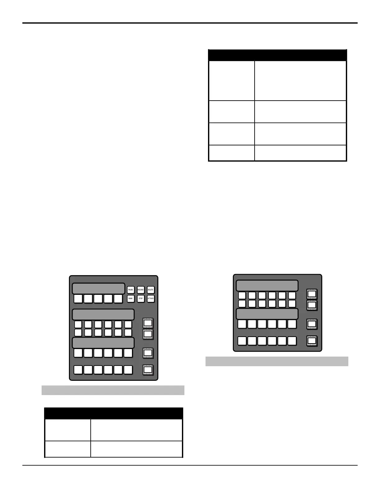
On the Double-Down panels there are six function
buttons to the right of the row that allow you to perform
specic custom control functions.
BANK ST OP ATTACH
PAUSE RECORD DELETE
Note: Double-Down module shown
Table 1: Custom Control Bus Function Buttons
FunctionButton
allows you to insert a pause or hold into
a custom control you are recording,
without using the menu system.
Pause (Hold)
allows you to record a custom control
without using the menu system.
Record
FunctionButton
allows you to delete a custom control.
Press and hold the Delete button and
press the custom control button for the
custom control you want to delete. Press
the custom control button again to confirm
the deletion.
Delete
allows you to select any custom control
bank without assigning each bank to a
custom control button.
Bank
allows you to stop a, or all, running custom
controls. The Stop CC command cannot
stop a custom control that is at hold.
Stop
allows you to turn the CC/Macro
Attachments personality option on or off.
Attach
Source Buses
These buttons are used to select sources on the buses that
the rows are assigned to. The lower two rows select
sources on the Background (upper) and Preset (lower)
buses of the ME that the row is assigned to. The upper
row(s) select sources on the key or aux buses that the
rows are assigned to.
The Double-Down control panel has two upper rows and
mnemonic buttons to the right of each row to show what
the button row is assigned to. The the standard control
panel only has a single row and a two-line display
showing how the buses are assigned.
Note: Double-Down module shown.
Refer to Panel Rows on page 18 for more information
on using the panel rows.
Fade to Black
This module is used to cut or dissolve the output of the
switcher to internally generated black. The display on
this module indicates the current rate for the fade to black
dissolve by default. When the switcher is at black, the
on-air source buttons and tallies ash.
Acuity Operation Manual (v9.2) — Acuity
®
Control Panel Overview • 13