Date Code 20010719 701 Motor Protection Relay
Section 5
Front-Panel Operation
Front-Panel Layout
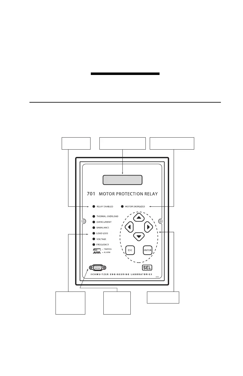
The SEL-701 Relay front-panel interface consists of LEDs, a vacuum fluorescent
display, a six-button keypad, and an EIA-232 serial port connector. The front-panel
layout is shown in Figure 5.1.
Figure 5.1 SEL-701 Relay Front Panel.
Vacuum Fluorescent Display
View real time and historic
information; enter relay settings.
EIA-232 Serial Port
Access all relay data,
control, and setting
functions quickly using
a PC, serial cable, and
the SEL-701PC software.
Trip/Alarm Target LEDs
Target LEDs flash to
indicate alarm
conditions; steady
on to indicate the
cause of the latest trip.
Relay Enabled LED
Lit when the
relay is operational.
Front-Panel Pushbutton
Control the
front-panel display.
Motor Energized LED
Flashes while the motor is starting;
steady on while the motor is running.