701 Motor Protection Relay Date Code 20010719
SEL
OGIC
®
Control Equations & Relay Logic
Selected Relay Logic Diagrams
B.32
Selected Relay Logic Diagrams
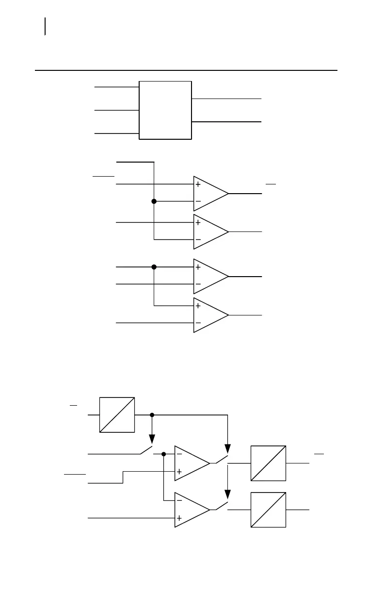
Figure B.9 Undervoltage Element Logic.
Figure B.10 Underpower Element Logic.
Voltage
Magnitude
Calculation
27P1
27P1P
|VP|
27P1
27P1P
27P2
|VPP|
VCA or VC
VBC or VB
VAB or VA
Relay
Word
Bits
|VP|
(Minimum Phase Voltage Magnitude)
|VPP|
(Minimum Phase-to-Phase Voltage Magnitude)
27P2
27P2P
27P2P
When DELTA_Y = Y:
Settings
When DELTA_Y = D:
37PAP
RUNNING
Measured
Real Power
Relay
Word
Bit
37DLY
0
Settings
37PAD
0
37PA
Relay
Word
Bits
37PTP
37PTD
0
37PT
Switches close when 37DLY expires