Date Code 20010719 701 Motor Protection Relay
Commissioning
Relay Commissioning Procedure
7.5
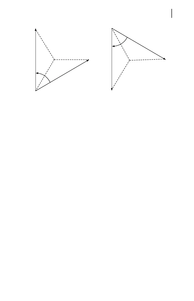
Figure 7.2 Open-Delta AC Potential Connection Test Signals.
Step 10. Verify contact input connections. Using the front-panel View Relay
Word\Row 10 function, check the contact input status in the relay
front-panel display. As you short-circuit each input, its label (IN1,
IN2, IN3, etc.) should appear in the front-panel display.
Step 11. Verify relay contact output electrical performance using the front-
panel Pulse Out Contact\TRIP command to close the TRIP output
contact. Repeat for the other output contacts. Make sure that each
contact operates properly in its designated annunciation, control, or
tripping circuit. See Section 5: Front-Panel Operation and Section 6:
ASCII Serial Port Operation for more details regarding the PULSE
command.
Step 12. Perform any desired protection element tests using the individual
element test procedures found in Selected Functional Tests on
page 7.8. Only perform enough tests to prove that the relay operates
as intended; exhaustive element performance characterizations are
not necessary for commissioning.
Step 13. Connect the relay for tripping duty. Verify that any settings changed
during the tests performed in Step 12 have been changed back to their
correct values for this application.
Step 14. Prepare the relay for operation by clearing the relay data buffers,
using the relay commands in Table 7.1. This prevents data generated
during installation testing from being confused with operational data
collected later.
60°
V
AB
V
CB
PHROT = ABC
60°
V
AB
V
CB
PHROT = ACB
When setting PHROT = ABC, set angle Ia
set angle Ib
set angle Ic
set angle Vab
set angle Vcb
= 0°
= -120°
= 120°
= +30°
= +90°
When setting PHROT = ACB, set angle Ia
set angle Ib
set angle Ic
set angle Vab
set angle Vcb
= 0°
= 120°
= -120°
= -30°
= -90°