701 Motor Protection Relay Date Code 20010719
Motor Thermal Element
The Basic Thermal Element
E.6
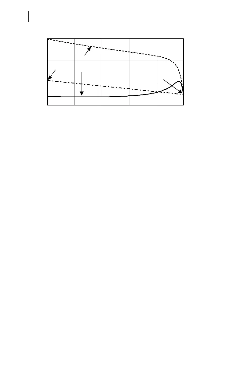
Figure E.3 Typical Induction Motor
Current, Torque, and Rotor Resistance versus Slip.
Figure E.3 shows a plot of a typical induction motor current, torque, and rotor
resistance versus slip. When motor slip is 1 per unit, rotor speed is zero. As the motor
approaches rated speed, slip decreases to near zero.
Calculate the positive-sequence rotor resistance plotted in Figure E.3 using
Equation E.2.
Equation E.2
Where:
S = Motor slip
Q
m
= Motor torque at slip S
I = Motor positive-sequence current at slip S
The positive-sequence rotor resistance is represented as a linear function of slip S
by Equation E.3.
Equation E.3
Where:
R
1
= Positive-sequence rotor resistance at slip S = 1
R
0
= Positive-sequence rotor resistance at slip S = 0
To properly account for the heating effects of the negative-sequence current,
calculate the negative-sequence rotor resistance. The rotor has slip with respect to the
stator negative-sequence current. To determine the value of the negative-sequence slip
as a function of positive-sequence slip, S, observe that negative-sequence stator
currents cause counter-rotating magnetic poles on the inside face of the stator. When
rotor speed is zero, the counter-rotating poles induce fundamental frequency currents
in the rotor: negative-sequence slip equals positive-sequence slip, S. When the rotor is
1 0.8 0.6 0.4 0.2
0
2
4
6
Slip, s
0
Current
Torque, Q
M
R
1
R
0
Per Unit
R
r
Q
M
I
2
--------
èø
ç÷
æö
S•=
R
r+
R
1
R
0
–()SR
0
+•=