Date Code 20010719 701 Motor Protection Relay
Installation
Relay Connections
2.15
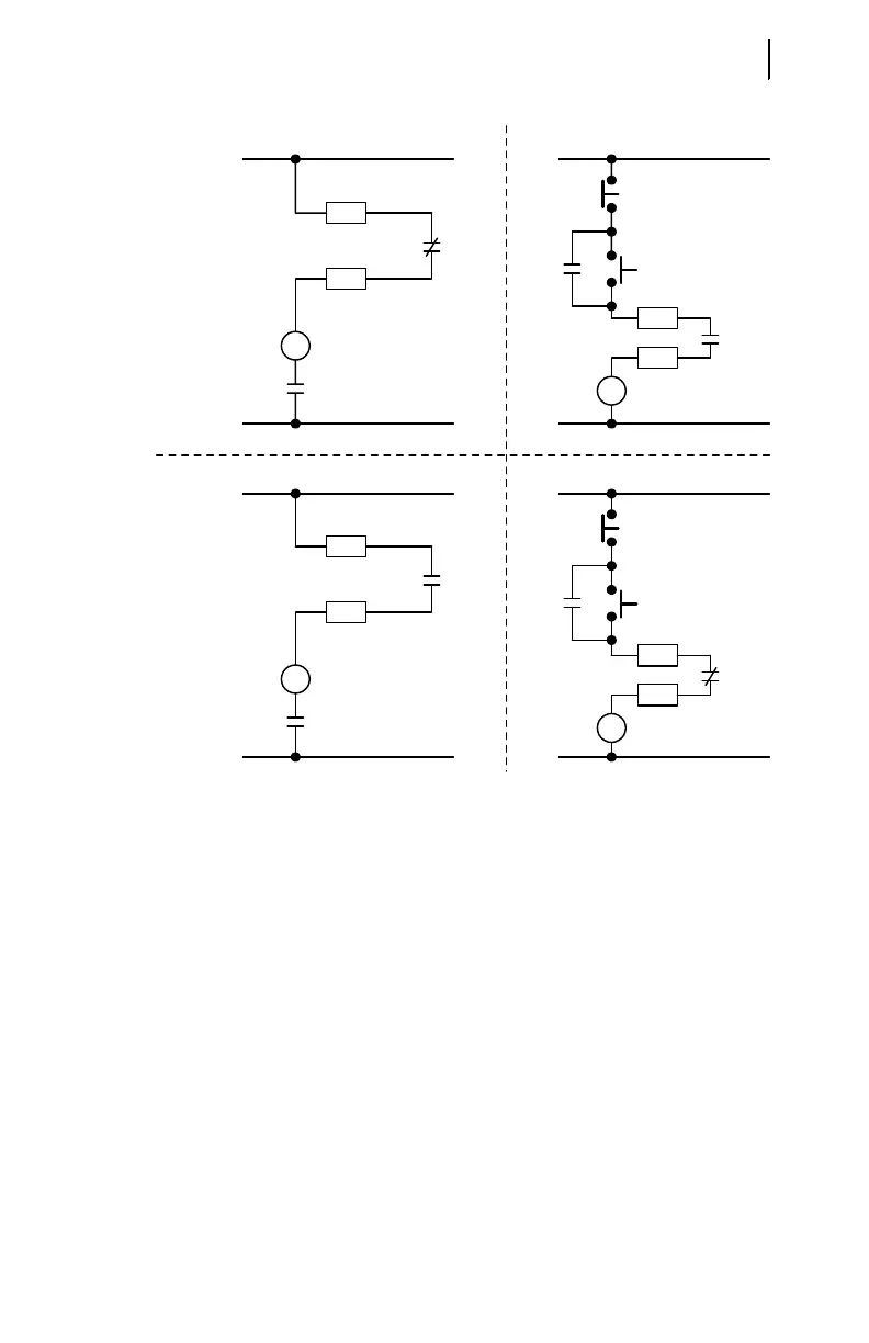
Figure 2.12 Trip Contact Fail-Safe, NonFail-Safe Wiring Options.
The relay output contacts are fully programmable using the relay settings
described in Appendix B: SELogic® Control Equations & Relay Logic. For many
applications, the factory default configuration will provide the desired performance.
The factory configuration for OUT1 provides an alarm for selected protection
elements such as the motor thermal element, load loss element, current unbalance
element, and power element alarms. The normally open output contact of OUT1 closes
if it detects any of these alarm conditions.
The factory configuration for OUT2 provides an alarm for RTD-based functions.
The relay closes the normally open output contact if an RTD alarm temperature is
exceeded, if the RTD Bias alarm picks up, if RTD leads short or open, or if the relay
loses communication with the SEL-2600 RTD Module. This output is inactive if the
relay is not equipped with RTD inputs.
Output OUT3 can be used to start the motor using the factory default settings as
shown in Figure 2.13.
B05
B06
TC
Trip
52A
B04
B05
CR
Trip
NonFail-Safe
Fail-Safe
Circuit Breaker Contactor
CR
STOP
START
B04
B05
TC
Trip
52A
Breaker Trip Coil
B05
B06
CR
Trip
CR
STOP
START
Contactor Coil
Contactor Coil
Breaker Trip Coil