701 Motor Protection Relay Date Code 20010719
Commissioning
Selected Functional Tests
7.14
NOTE: Changing settings requires that you enter the Access
Level 2 password. The factory password is 701.
Step 3. Set the current source phase angles to apply balanced three-phase
currents. Refer to Figure 7.1 on page 7.4 for the correct angles, which
depend on the PHROT setting.
Step 4. Reset the motor thermal element using the front-panel Reset Thermal
Model function.
NOTE: This function requires that you enter the Access Level 2
password. The factory password is 701.
Set the current sources to apply the test current shown in Table 7.6,
then turn on the current sources together. Refer back to Table 7 .6 to
determine the expected element operating time. For instance, when
the setting CURVE is equal to 4, the thermal element should trip in
4•10 = 40 seconds when applied three-phase current equals three
times the motor full load current setting, FLA. Use the front-panel
Meter Values\Thermal & RTD Data function to view the estimated
Time to Thermal Trip during each test.
NOTE: Reset the motor thermal model before each test run or
the element will trip faster than expected.
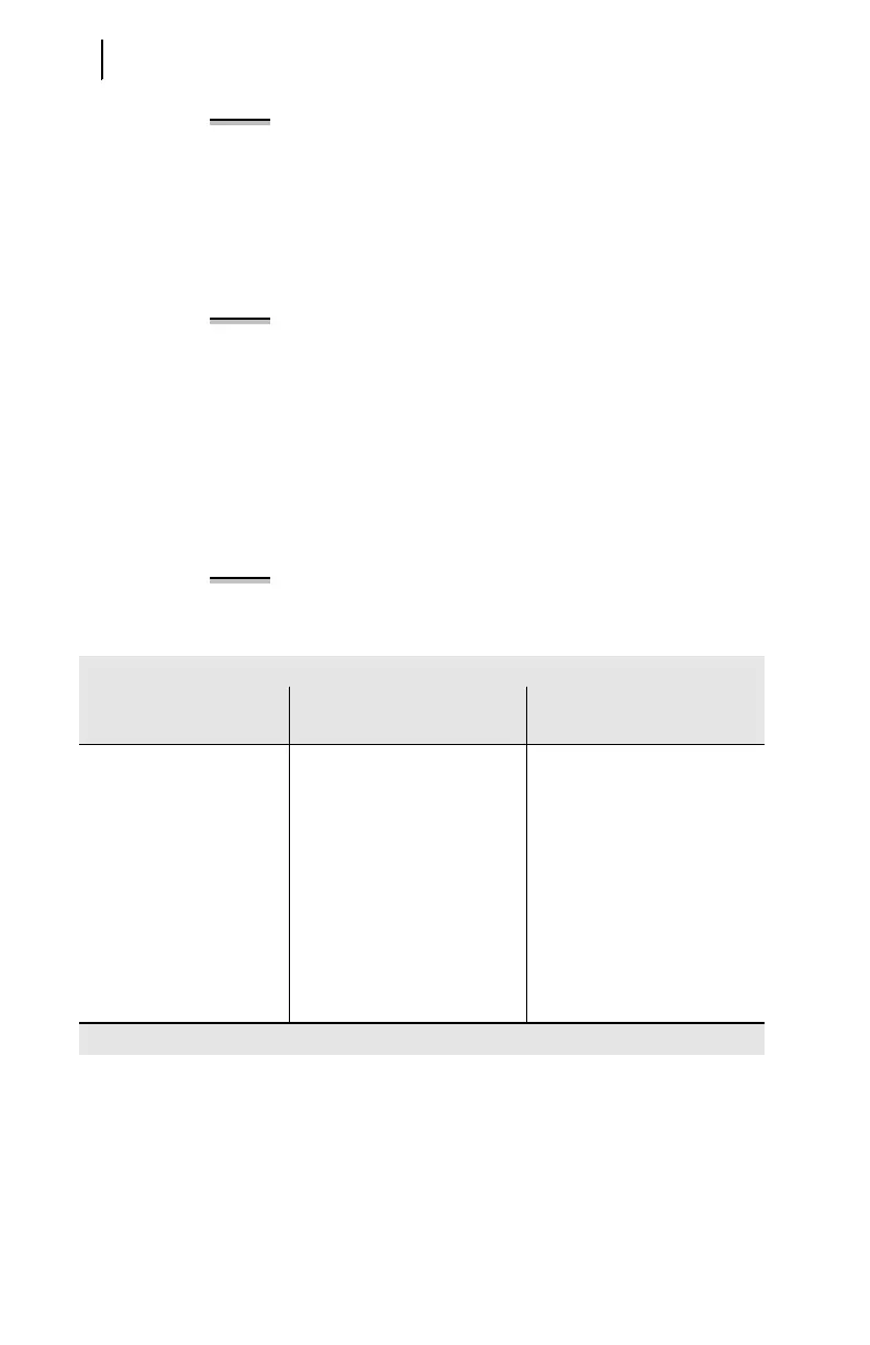
Table 7.6 Th erma l Element Ex pected Trip Times
Table 7.6 Thermal Element Expected Trip Times
Applied
Current (A secondary)
Expected Time to Trip (s)
Measured Time to Trip (s)
1.2 • FLA CURVE • 145.7
1.5 • FLA CURVE • 51.5
2.0 • FLA CURVE • 23.3
3.0 • FLA CURVE • 10.0
4.0 • FLA CURVE • 5.63
5.0 • FLA CURVE • 3.60
6.0 • FLA CURVE • 2.50
7.0 • FLA CURVE • 1.84