701 Motor Protection Relay Date Code 20010719
Metering & Monitoring
Power Measurement Conventions
8.6
Power Measurement Conventions
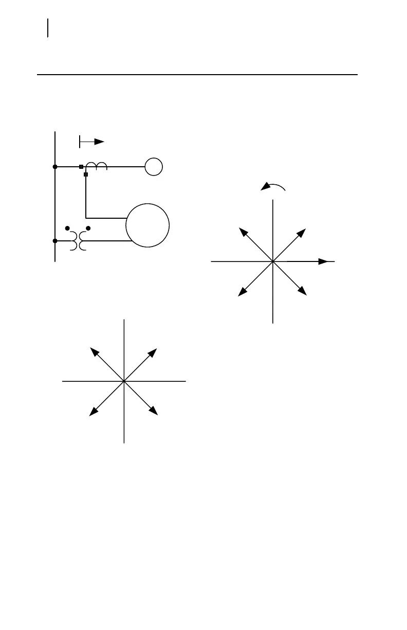
The SEL-701 Relay uses the IEEE convention for power measurement assuming
motor action. The implications of this convention are described by Figure 8.1.
Figure 8.1 Power Measurement Conventions.
In the SEL-701 Relay, reported positive real power and energy are always into the
motor.
Power Plane
S2 = VI
2
*
Q+
Q–
+PP–
S1 = VI
2
*
S4 = VI
4
*S3 = VI
3
*
I
2
Phasor Diagram
Positive Phase Rotation
I
1
I
3
I
4
I leads V
W = –
VAR = –
PF = LAG
+90°
–90°
I lags V
W = –
VAR = +
PF = LEAD
+0°+180°
I leads V
W = +
VAR = –
PF = LEAD
I lags V
W = +
VAR = +
PF = LAG
Bus Voltage, V
M
SEL-701
Relay
Source
Bus
Direction of
Positive Real Power
Motor