Date Code 20010719 701 Motor Protection Relay
Installation
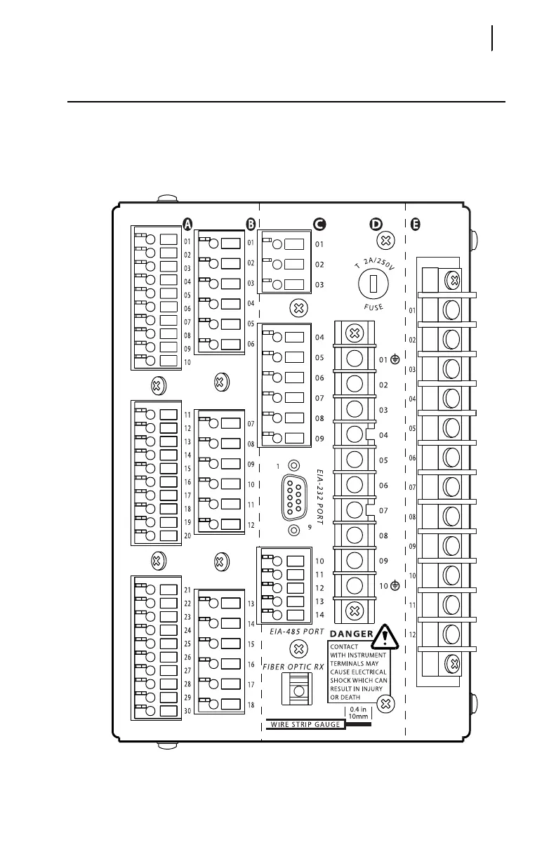
Relay Rear-Panel Diagram
2.5
Relay Rear-Panel Diagram
All relay electrical connections, except the front-panel EIA-232 connections, are
made at the relay rear panel, shown in Figure 2.4. The relay rear panel is designed with
two 45° sections illustrated in Figure 2.1 on page 2.2. These cutaway areas provide
additional clearance for swing-panel mounting. The relay sides include drawings that
indicate the factory default function of each relay terminal and typical wiring diagrams.
Figure 2.4 SEL-701 Relay Rear Panel.