Date Code 20010719 701 Motor Protection Relay
SELOGIC
®
Control Equations & Relay Logic
Latch Control Switch Settings
B.17
Latch Control Switch Settings
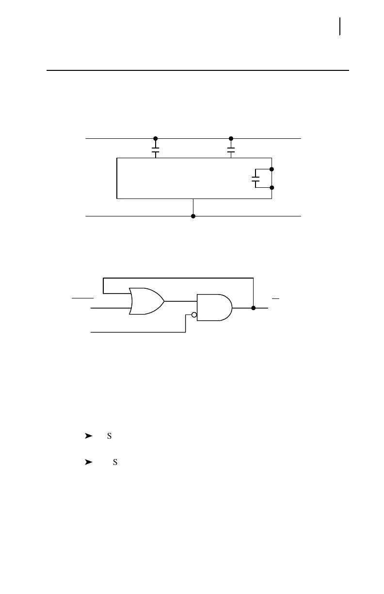
The latch control switch feature of the SEL-701 Relay replaces latching relays.
The state of a traditional latching relay output contact is changed by pulsing the
latching relay inputs. (See Figure B.4). Pulse the set input to close (set) the latching
relay output contact. Pulse the reset input to open (reset) the latching relay output
contact.
Figure B.4 Traditional Latching Relay.
Four latch control switches in the SEL-701 Relay provide latching relay type
functions.
Figure B.5 Latch Control Switches Drive Latch Bits LT1 through LT4.
The output of the latch control switch in Figure B.5 is a Relay Word bit LTn
(n = 1–4), called a latch bit. The latch control switch logic in Figure B.5 repeats for
each latch bit LT1 through LT4. Use these latch bits in SEL
OGIC control equations.
These latch control switches each have the following SELOGIC control equation
settings:
SETn sets latch bit LTn to logical 1 when SETn SELOGIC control
equation result is logical 1.
RSTn reset latch bit LTn to logical 0 when RSTn SELOGIC control
equation result is logical 1.
If both SETn and RSTn assert to logical 1, RSTn has priority and latch bit LTn
deasserts to logical 0.
(+)
–
Reset Input
Traditional
Latching Relay
Set Input
Output
Contact
LTn
(set)
(reset) (n = 1 through 4)
SEL
OGIC
Settings
Relay
Word
Bit
SETn
RSTn