701 Motor Protection Relay Date Code 20010719
SEL
OGIC
®
Control Equations & Relay Logic
Remote Control Switches
B.30
Remote Control Switches
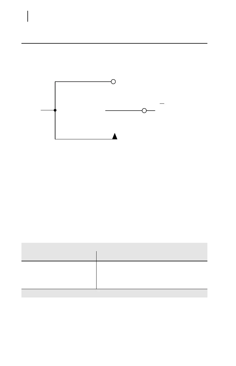
Remote control switches do not have settings; they are operated via the serial
communications port only (see CONTROL (Level 2) on page 6.12 in Section 6: ASCII
Serial Port Operation).
Figure B.8 Remote Control
Switches Drive Remote Bits RB1 through RB4.
The outputs of the remote control switches in Figure B.8 are Relay Word bits RBn
(n = 1–4), called remote bits. Use these remote bits in SEL
OGIC control equations.
Any given remote control switch can be put in one of three positions shown in
Table B.4.
Table B.4 Remote Control Switch
RBn
Logical 1
(n = 1 through 4)
ON position
(maintained logical 1 position)
The switch representation in this figure is derived from the standard:
Graphics Symbols for Electrical and Electronics Diagrams
IEEE Std 315-1975, CSA Z99-1975, ANSI Y32.2-1975,
4.11 Combination Locking and Nonlocking Switch, Item 4.11.1
OFF position
(maintained logical 0 position)
MOMENTARY position
(logical 1 for one processing interval)
Relay
Word
Bit
Table B.4 Remote Control Switch
Control Switch Position Description
ON logical 1
OFF logical 0
MOMENTARY logical 1 for one processing interval



 To Next Page