Date Code 20010719 701 Motor Protection Relay
Motor Thermal Element
The Basic Thermal Element
E.5
The Basic Thermal Element
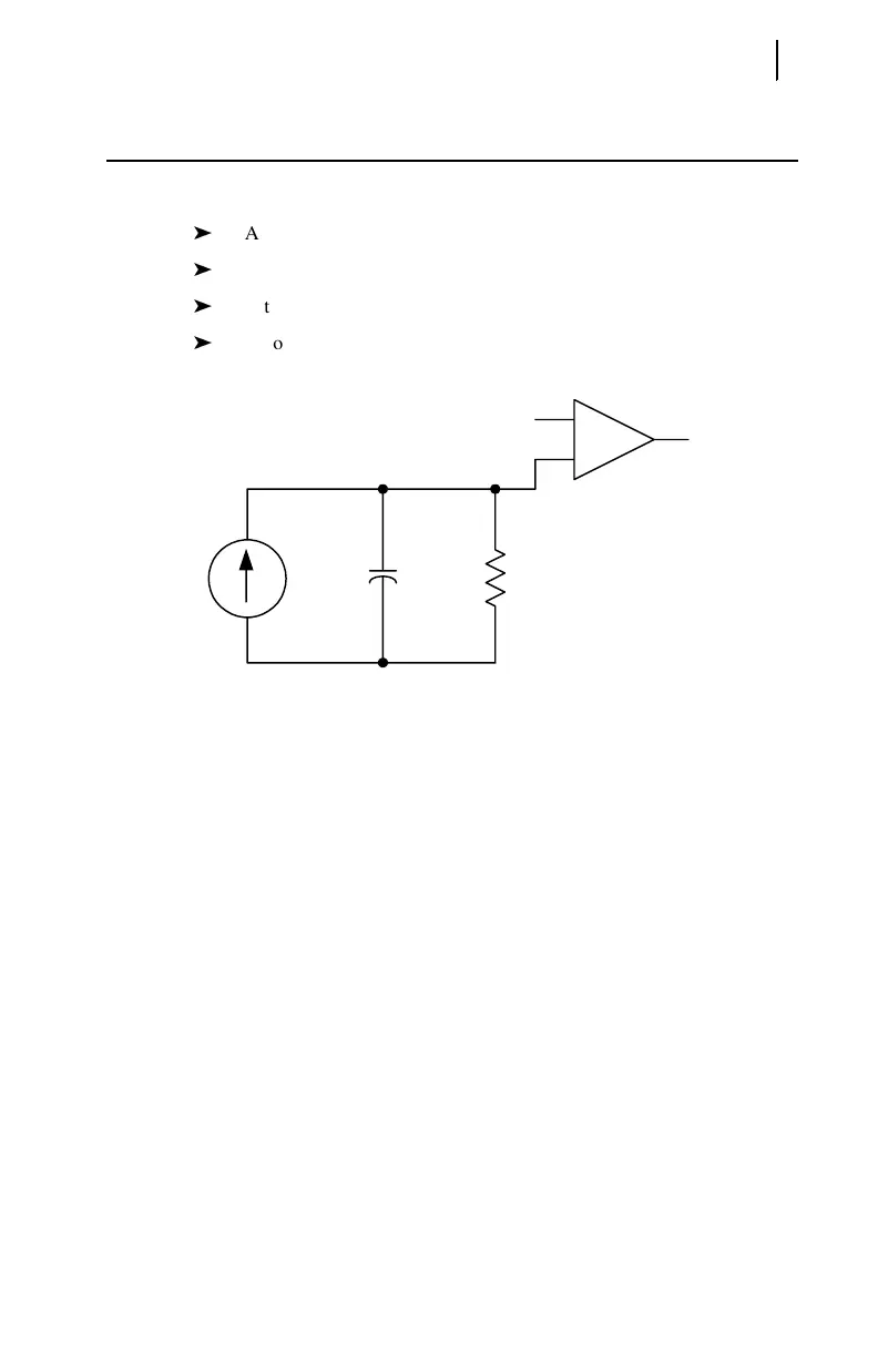
Figure E.2 shows a simple electrical analog for a thermal system. The thermal
element includes:
A heat source, modeled as a current source.
A thermal capacitance, modeled as a capacitor.
A thermal impedance to ambient, modeled as a resistor.
A comparator, to compare the present heat estimate, U, to the
Thermal Trip Value.
Figure E.2 Electrical Analog of a Thermal System.
In order to define a thermal element for an induction motor, the characteristics of
each component in Figure E.2 must be defined, starting with the heat source. In an
induction motor, heat principally is caused by I
2
r losses. To consider the effects of
negative-sequence current on the motor, it is called out separately in Equation E.1.
Equation E.1
Heating factors K
1
and K
2
are defined by the positive-sequence rotor resistance
and negative-sequence rotor resistance, respectively.
Thermal Trip
Thermal Trip Value
_
+
Heat
Source
U
CR
Heat Source I
1
2
K
1
• I
2
2
K
2
•+=