6.5
Date Code 20090730 Instruction Manual SEL-734 Meter
Power Quality and Event Analysis
Event Reports
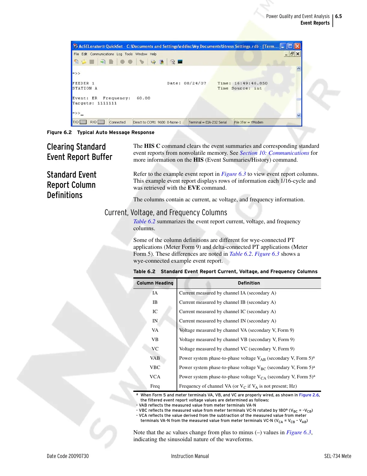
Figure 6.2 Typical Auto Message Response
Clearing Standard
Event Report Buffer
The HIS C command clears the event summaries and corresponding standard
event reports from nonvolatile memory. See Section 10: Communications for
more information on the HIS (Event Summaries/History) command.
Standard Event
Report Column
Definitions
Refer to the example event report in Figure 6.3 to view event report columns.
This example event report displays rows of information each 1/16-cycle and
was retrieved with the EVE command.
The columns contain ac current, ac voltage, and frequency information.
Current, Voltage, and Frequency Columns
Table 6.2 summarizes the event report current, voltage, and frequency
columns.
Some of the column definitions are different for wye-connected PT
applications (Meter Form 9) and delta-connected PT applications (Meter
Form 5). These differences are noted in Table 6.2. Figure 6.3 shows a
wye-connected example event report.
Note that the ac values change from plus to minus (–) values in Figure 6.3,
indicating the sinusoidal nature of the waveforms.
Table 6.2 Standard Event Report Current, Voltage, and Frequency Columns
Column Heading Definition
IA Current measured by channel IA (secondary A)
IB Current measured by channel IB (secondary A)
IC Current measured by channel IC (secondary A)
IN Current measured by channel IN (secondary A)
VA Voltage measured by channel VA (secondary V, Form 9)
VB Voltage measured by channel VB (secondary V, Form 9)
VC Voltage measured by channel VC (secondary V, Form 9)
VAB Power system phase-to-phase voltage V
AB
(secondary V, Form 5)
a
a
When Form 5 and meter terminals VA, VB, and VC are properly wired, as shown in Figure 2.6,
the filtered event report voltage values are determined as follows:
- VAB reflects the measured value from meter terminals VA-N
- VBC reflects the measured value from meter terminals VC-N rotated by 180° (V
BC
= –V
CB
)
- VCA reflects the value derived from the subtraction of the measured value from meter
terminals VA-N from the measured value from meter terminals VC-N (V
CA
= V
CB
– V
AB
)
VBC Power system phase-to-phase voltage V
BC
(secondary V, Form 5)
a
VCA Power system phase-to-phase voltage V
CA
(secondary V, Form 5)
a
Freq Frequency of channel VA (or V
C
if V
A
is not present; Hz)
Courtesy of NationalSwitchgear.com