2.10
SEL-734 Meter Instruction Manual Date Code 20090730
Installation
Making Rear-Panel Connections
Form 5 Voltages
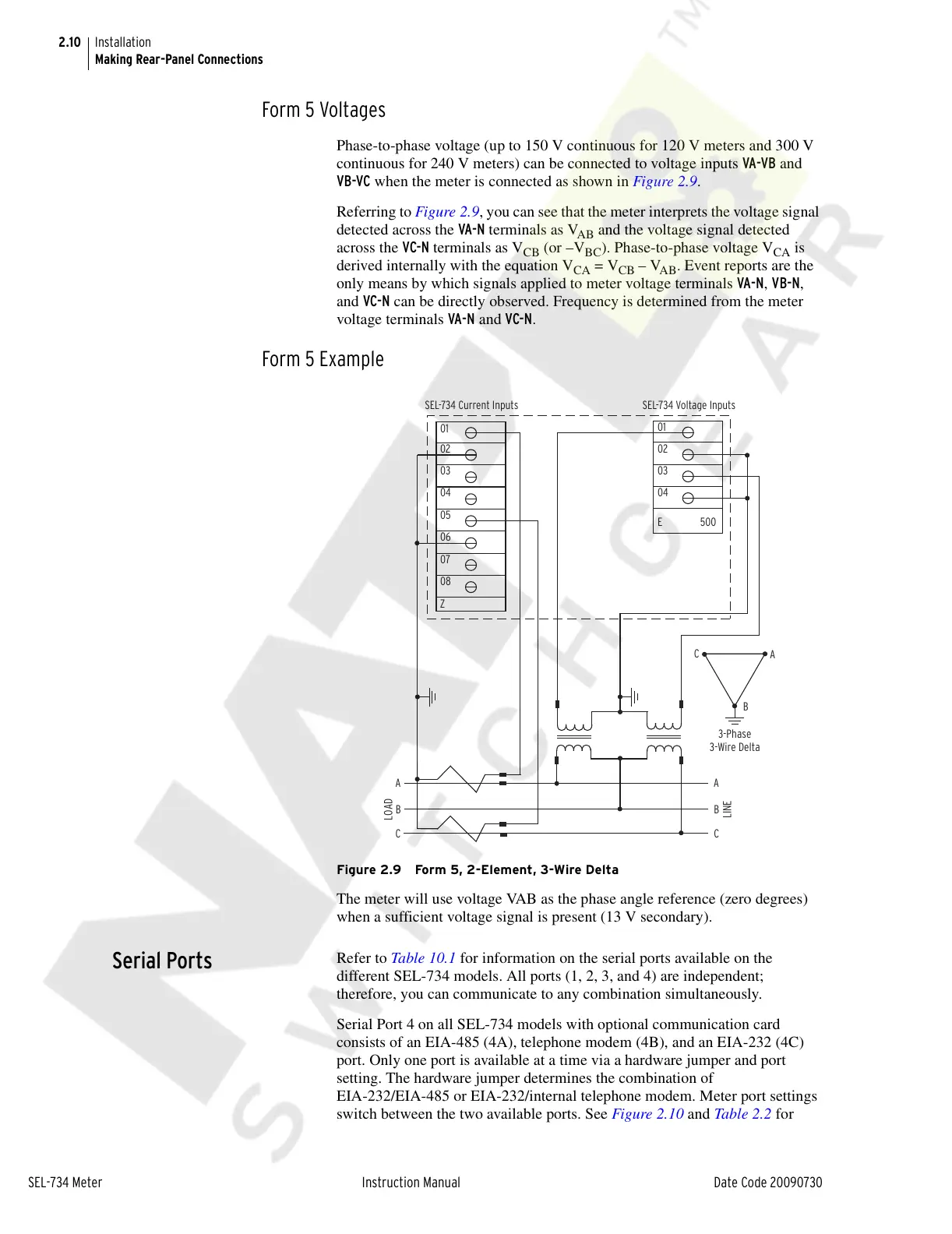
Phase-to-phase voltage (up to 150 V continuous for 120 V meters and 300 V
continuous for 240 V meters) can be connected to voltage inputs VA-VB and
VB-VC when the meter is connected as shown in Figure 2.9.
Referring to Figure 2.9, you can see that the meter interprets the voltage signal
detected across the VA-N terminals as V
AB
and the voltage signal detected
across the VC-N terminals as V
CB
(or –V
BC
). Phase-to-phase voltage V
CA
is
derived internally with the equation V
CA
= V
CB
– V
AB
. Event reports are the
only means by which signals applied to meter voltage terminals VA-N, VB-N,
and VC-N can be directly observed. Frequency is determined from the meter
voltage terminals VA-N and VC-N.
Form 5 Example
Figure 2.9 Form 5, 2-Element, 3-Wire Delta
The meter will use voltage VAB as the phase angle reference (zero degrees)
when a sufficient voltage signal is present (13 V secondary).
Serial Ports
Refer to Table 10.1 for information on the serial ports available on the
different SEL-734 models. All ports (1, 2, 3, and 4) are independent;
therefore, you can communicate to any combination simultaneously.
Serial Port 4 on all SEL-734 models with optional communication card
consists of an EIA-485 (4A), telephone modem (4B), and an EIA-232 (4C)
port. Only one port is available at a time via a hardware jumper and port
setting. The hardware jumper determines the combination of
EIA-232/EIA-485 or EIA-232/internal telephone modem. Meter port settings
switch between the two available ports. See Figure 2.10 and Table 2.2 for
A
B
C
3-Phase
3-Wire Delta
C
B
LINE
LOAD
A
01
02
03
04
E
01
02
03
04
05
06
07
08
Z
C
B
A
500
SEL-734 Current Inputs SEL-734 Voltage Inputs
Courtesy of NationalSwitchgear.com