7.9
Date Code 20090730 Instruction Manual SEL-734 Meter
Time-Synchronized Measurements
Power Flow Analysis
Power Flow Analysis
Use the meter to develop instantaneous power flow data. Obtain the voltage
and current phasors from different power system buses at the same instant and
use these measurements to determine power flow at that moment in time.
Use the synchronized phasor measurement capabilities of the meter to collect
synchronized voltage and current data. Use this information to confirm your
power flow models.
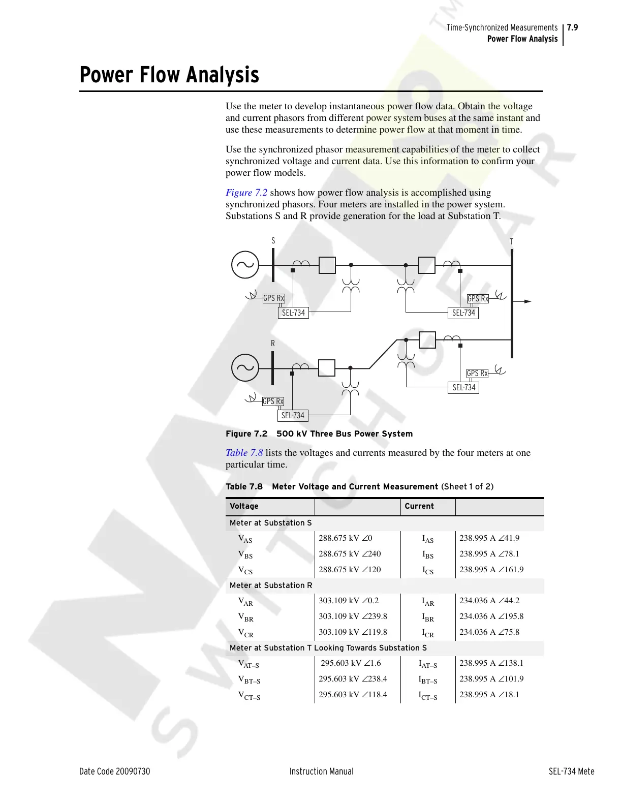
Figure 7.2 shows how power flow analysis is accomplished using
synchronized phasors. Four meters are installed in the power system.
Substations S and R provide generation for the load at Substation T.
Figure 7.2 500 kV Three Bus Power System
Table 7.8 lists the voltages and currents measured by the four meters at one
particular time.
Table 7.8 Meter Voltage and Current Measurement (Sheet 1 of 2)
Voltage Current
Meter at Substation S
V
AS
288.675 kV ∠0 I
AS
238.995 A ∠41.9
V
BS
288.675 kV ∠240 I
BS
238.995 A ∠78.1
V
CS
288.675 kV ∠120 I
CS
238.995 A ∠161.9
Meter at Substation R
V
AR
303.109 kV ∠0.2 I
AR
234.036 A ∠44.2
V
BR
303.109 kV ∠239.8 I
BR
234.036 A ∠195.8
V
CR
303.109 kV ∠119.8 I
CR
234.036 A ∠75.8
Meter at Substation T Looking Towards Substation S
V
AT – S
295.603 kV ∠1.6 I
AT– S
238.995 A ∠138.1
V
BT–S
295.603 kV ∠238.4 I
BT–S
238.995 A ∠101.9
V
CT–S
295.603 kV ∠118.4 I
CT–S
238.995 A ∠18.1
S
T
SEL-734
GPS Rx
SEL-734
GPS Rx
SEL-734
GPS Rx
R
SEL-734
GPS Rx
Courtesy of NationalSwitchgear.com