8.2
SEL-734 Meter Instruction Manual Date Code 20090730
Logic
Optoisolated Inputs
Optoisolated Inputs
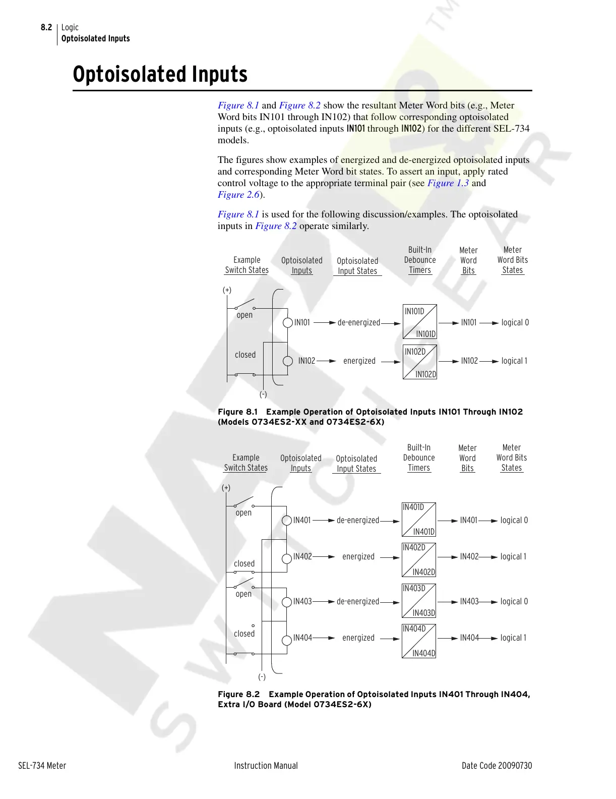
Figure 8.1 and Figure 8.2 show the resultant Meter Word bits (e.g., Meter
Word bits IN101 through IN102) that follow corresponding optoisolated
inputs (e.g., optoisolated inputs IN101 through IN102) for the different SEL-734
models.
The figures show examples of energized and de-energized optoisolated inputs
and corresponding Meter Word bit states. To assert an input, apply rated
control voltage to the appropriate terminal pair (see Figure 1.3 and
Figure 2.6).
Figure 8.1 is used for the following discussion/examples. The optoisolated
inputs in Figure 8.2 operate similarly.
Figure 8.1 Example Operation of Optoisolated Inputs IN101 Through IN102
(Models 0734ES2-XX and 0734ES2-6X)
Figure 8.2 Example Operation of Optoisolated Inputs IN401 Through IN404,
Extra I/O Board (Model 0734ES2-6X)
open
closed
Example
Switch States
Optoisolated
Input States
Optoisolated
Inputs
Built-In
Debounce
Timers
Meter
Word
Bits
Meter
Word Bits
States
IN101 de-energized IN101 logical 0
energizedIN102 IN102 logical 1
(+)
(-)
IN101D
IN101D
IN102D
IN102D
Example
Switch States
Optoisolated
Input States
Optoisolated
Inputs
Built-In
Debounce
Timers
Meter
Word
Bits
Meter
Word Bits
States
open
closed
IN401 de-energized IN401 logical 0
energizedIN402 IN402 logical 1
(+)
IN401D
IN401D
IN402D
IN402D
open
closed
IN403 de-energized IN403 logical 0
energizedIN404 IN404 logical 1
(-)
IN403D
IN403D
IN404D
IN404D
Courtesy of NationalSwitchgear.com