12.3
Date Code 20090730 Instruction Manual SEL-734 Meter
Testing and Troubleshooting
Testing Methods and Tools
Testing Methods and Tools
Test Features
Provided by the
Meter
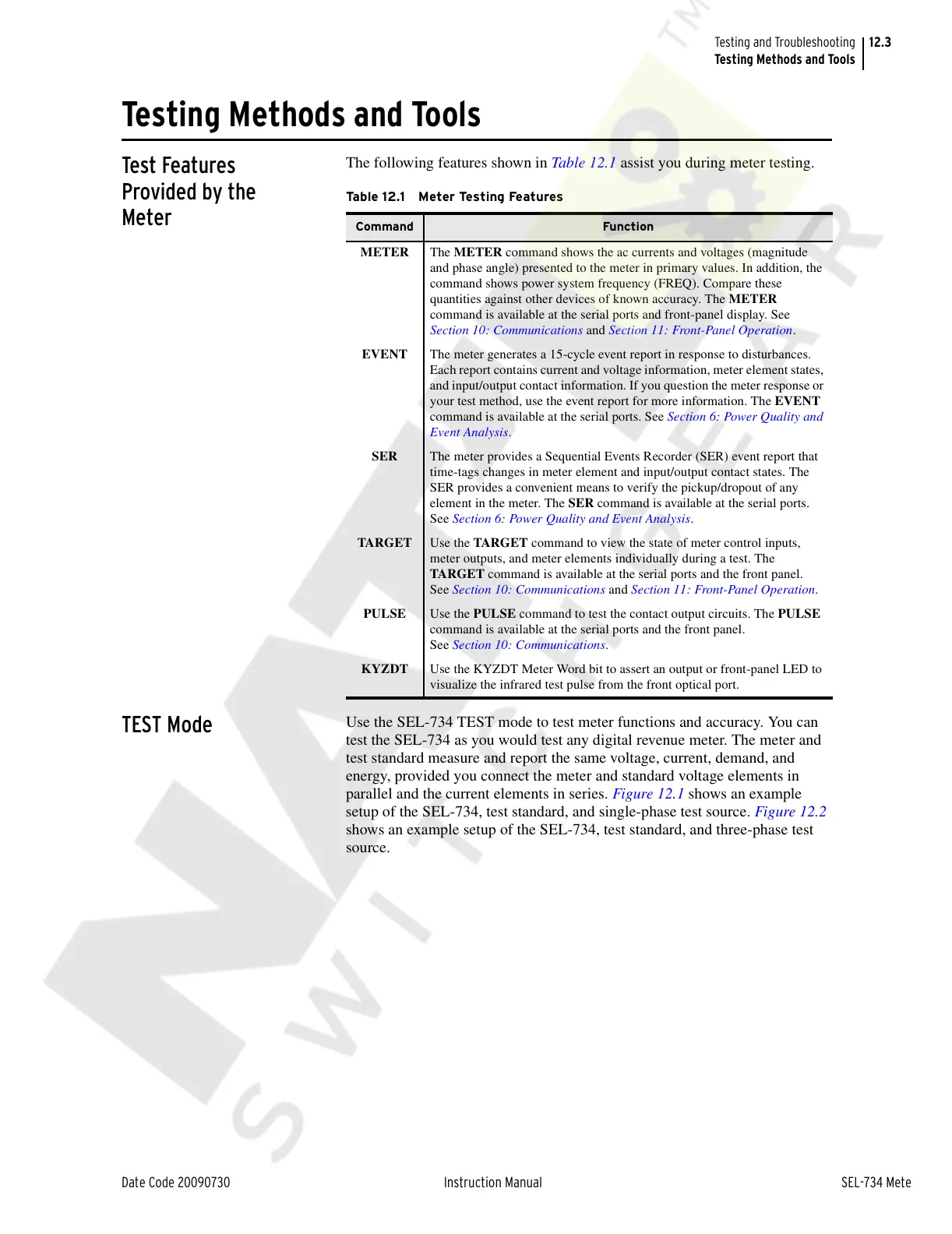
The following features shown in Table 12.1 assist you during meter testing.
TEST Mode
Use the SEL-734 TEST mode to test meter functions and accuracy. You can
test the SEL-734 as you would test any digital revenue meter. The meter and
test standard measure and report the same voltage, current, demand, and
energy, provided you connect the meter and standard voltage elements in
parallel and the current elements in series. Figure 12.1 shows an example
setup of the SEL-734, test standard, and single-phase test source. Figure 12.2
shows an example setup of the SEL-734, test standard, and three-phase test
source.
Ta b l e 1 2 . 1 M e t e r Te st i n g Fe a t u re s
Command Function
METER The METER command shows the ac currents and voltages (magnitude
and phase angle) presented to the meter in primary values. In addition, the
command shows power system frequency (FREQ). Compare these
quantities against other devices of known accuracy. The METER
command is available at the serial ports and front-panel display. See
Section 10: Communications and Section 11: Front-Panel Operation.
EVENT The meter generates a 15-cycle event report in response to disturbances.
Each report contains current and voltage information, meter element states,
and input/output contact information. If you question the meter response or
your test method, use the event report for more information. The EVENT
command is available at the serial ports. See Section 6: Power Quality and
Event Analysis.
SER The meter provides a Sequential Events Recorder (SER) event report that
time-tags changes in meter element and input/output contact states. The
SER provides a convenient means to verify the pickup/dropout of any
element in the meter. The SER command is available at the serial ports.
See Section 6: Power Quality and Event Analysis.
TARGET Use the TARGET command to view the state of meter control inputs,
meter outputs, and meter elements individually during a test. The
TARGET command is available at the serial ports and the front panel.
See Section 10: Communications and Section 11: Front-Panel Operation.
PULSE Use the PULSE command to test the contact output circuits. The PULSE
command is available at the serial ports and the front panel.
See Section 10: Communications.
KYZDT Use the KYZDT Meter Word bit to assert an output or front-panel LED to
visualize the infrared test pulse from the front optical port.
Courtesy of NationalSwitchgear.com