8.5
Date Code 20090730 Instruction Manual SEL-734 Meter
Logic
Latch Bits
If RB03 is initially at logical 0, pulsing it with the CON 3 command and
PRB 3 subcommand will change RB03 to logical 1 for one processing
interval, and then return it to logical 0. In this situation, the R_TRIG RB03
(rising edge operator) will also assert for one processing interval, followed by
the F_TRIG RB03 (falling edge operator) one processing interval later.
If RB03 is initially at logical 1 instead, pulsing it with the CON 3 command
and PRB 3 subcommand will change RB03 to a logical 0. In this situation, the
R_TRIG RB03 (rising edge operator) will not assert, but the F_TRIG RB03
(falling edge operator) will assert for one processing interval.
Latch Bits
Latch control switches (Latch Bits are the outputs of these switches) replace
traditional latching relays. Traditional latching relays maintain their output
contact state. The SEL-734 latch control switches retain their state even when
power to the meter is lost. If the latch control switch is set to a programmable
output contact and power to the meter is lost, the state of the latch control
switch is stored in nonvolatile memory, but the output contact will go to its
de-energized state. When power to the meter is restored, the programmable
output contact will go back to the state of the latch control switch after meter
initialization.
Traditional latching relay output contact states are changed by pulsing the
latching relay inputs (see Figure 8.4). Pulse the set input to close (set) the
latching relay output contact. Pulse the reset input to open (reset) the latching
relay output contact. Often the external contacts wired to the latching relay
inputs are from remote control equipment (e.g., SCADA, RTU).
Figure 8.4 Traditional Latching Relay
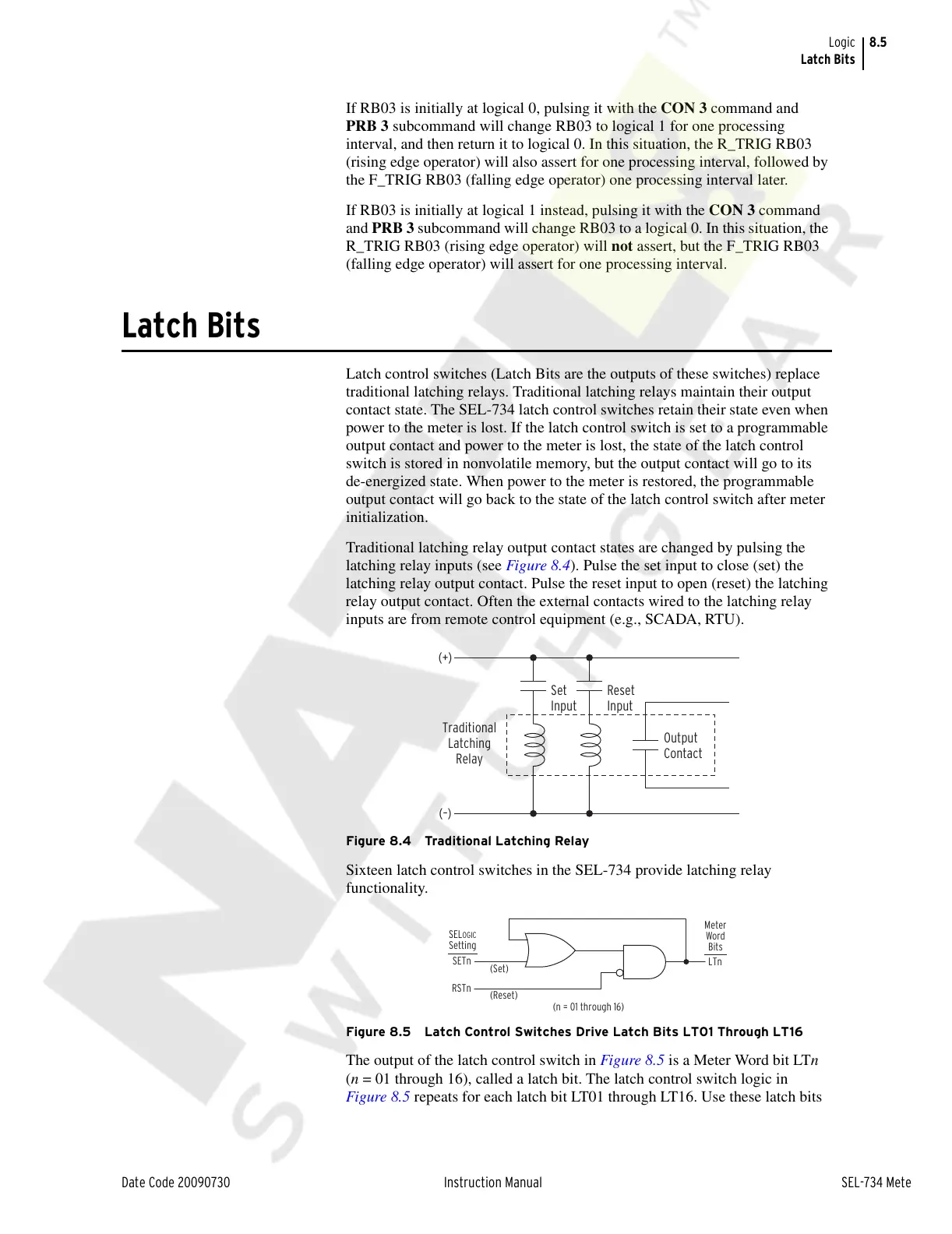
Sixteen latch control switches in the SEL-734 provide latching relay
functionality.
Figure 8.5 Latch Control Switches Drive Latch Bits LT01 Through LT16
The output of the latch control switch in Figure 8.5 is a Meter Word bit LTn
(n = 01 through 16), called a latch bit. The latch control switch logic in
Figure 8.5 repeats for each latch bit LT01 through LT16. Use these latch bits
Set
Input
Reset
Input
Output
Contact
Traditional
Latching
Relay
(+)
(–)
LTn
SETn
RSTn
(Set)
(Reset)
(n = 01 through 16)
Meter
Word
Bits
SELOGIC
Setting
Courtesy of NationalSwitchgear.com