4.26
SEL-734 Meter Instruction Manual Date Code 20090730
Metering
Transformer/Line Loss Compensation
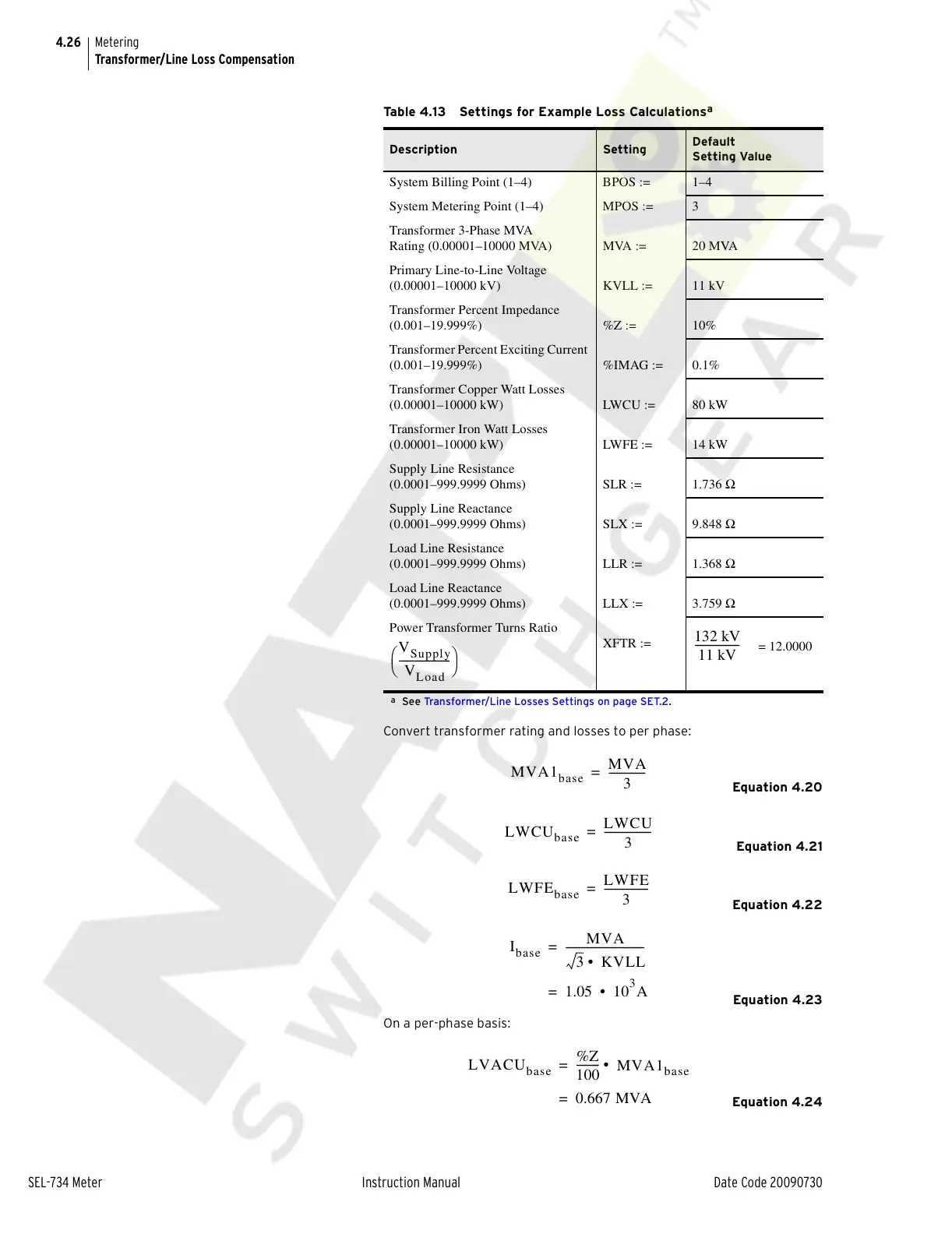
Convert transformer rating and losses to per phase:
Equation 4.20
Equation 4.21
Equation 4.22
Equation 4.23
On a per-phase basis:
Equation 4.24
Table 4.13 Settings for Example Loss Calculations
a
a
See Transformer/Line Losses Settings on page SET.2.
Description Setting
Default
Setting Value
System Billing Point (1–4) BPOS := 1–4
System Metering Point (1–4) MPOS := 3
Transformer 3-Phase MVA
Rating (0.00001–10000 MVA) MVA := 20 MVA
Primary Line-to-Line Voltage
(0.00001–10000 kV) KVLL := 11 kV
Transformer Percent Impedance
(0.001–19.999%) %Z := 10%
Transformer Percent Exciting Current
(0.001–19.999%) %IMAG := 0.1%
Transformer Copper Watt Losses
(0.00001–10000 kW) LWCU := 80 kW
Transformer Iron Watt Losses
(0.00001–10000 kW) LWFE := 14 kW
Supply Line Resistance
(0.0001–999.9999 Ohms) SLR := 1.736 Ω
Supply Line Reactance
(0.0001–999.9999 Ohms) SLX := 9.848 Ω
Load Line Resistance
(0.0001–999.9999 Ohms) LLR := 1.368 Ω
Load Line Reactance
(0.0001–999.9999 Ohms) LLX := 3.759 Ω
Power Transformer Turns Ratio
XFTR :=
= 12.0000
V
Supply
V
Load
--------------------
⎝⎠
⎛⎞
132 kV
11 kV
-----------------
MVA1
base
MVA
3
--------------=
LWCU
base
LWCU
3
------------------=
LWFE
base
LWFE
3
-----------------=
I
base
MVA
3 KVLL•
------------------------------=
1.05 =10
3
A•
LVACU
base
%Z
100
---------
MVA1
base
• =
0.667 MVA=
Courtesy of NationalSwitchgear.com