2.9
Date Code 20090730 Instruction Manual SEL-734 Meter
Installation
Making Rear-Panel Connections
Potential
Transformer Inputs
Note the signal labels (V
A
, V
B
, V
C
) on terminals E01 through E04.
Determining the Voltage Input Rating
The serial number sticker on the meter rear panel indicates the continuous
voltage input rating. The part number also contains the voltage rating
information.
This voltage rating applies to the three-phase voltage inputs (V
A-N
, V
B-N
,
V
C-N
). The voltage rating is in units of V
L-N
when the meter is Form 9
(three-phase, four-wire), or V
L-L
when the meter is Form 5 (three-phase,
three-wire). The following two subsections explain the Form 5 and Form 9
voltage input connections.
Form 9 Voltages
NOTE: “3V0” in the MET command
(via serial port or front panel) is
derived internally from the VA, VB, and
VC voltage inputs.
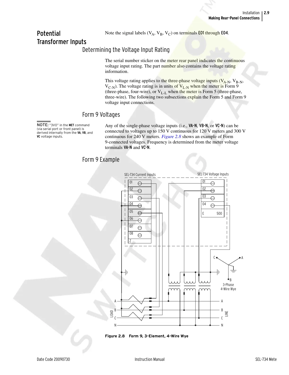
Any of the single-phase voltage inputs (i.e., VA-N, VB-N, or VC-N) can be
connected to voltages up to 150 V continuous for 120 V meters and 300 V
continuous for 240 V meters. Figure 2.8 shows an example of Form
9-connected voltages. Frequency is determined from the meter voltage
terminals VA-N and VC-N.
Form 9 Example
Figure 2.8 Form 9, 3-Element, 4-Wire Wye
N
C
B
LINE
LOAD
A
B
C
3-Phase
4-Wire Wye
A
01
02
03
04
E
01
02
03
04
05
06
07
08
Z
N
C
B
A
500
SEL-734 Current Inputs
SEL-734 Voltage Inputs
Courtesy of NationalSwitchgear.com