8.8
SEL-734 Meter Instruction Manual Date Code 20090730
Logic
Latch Bits
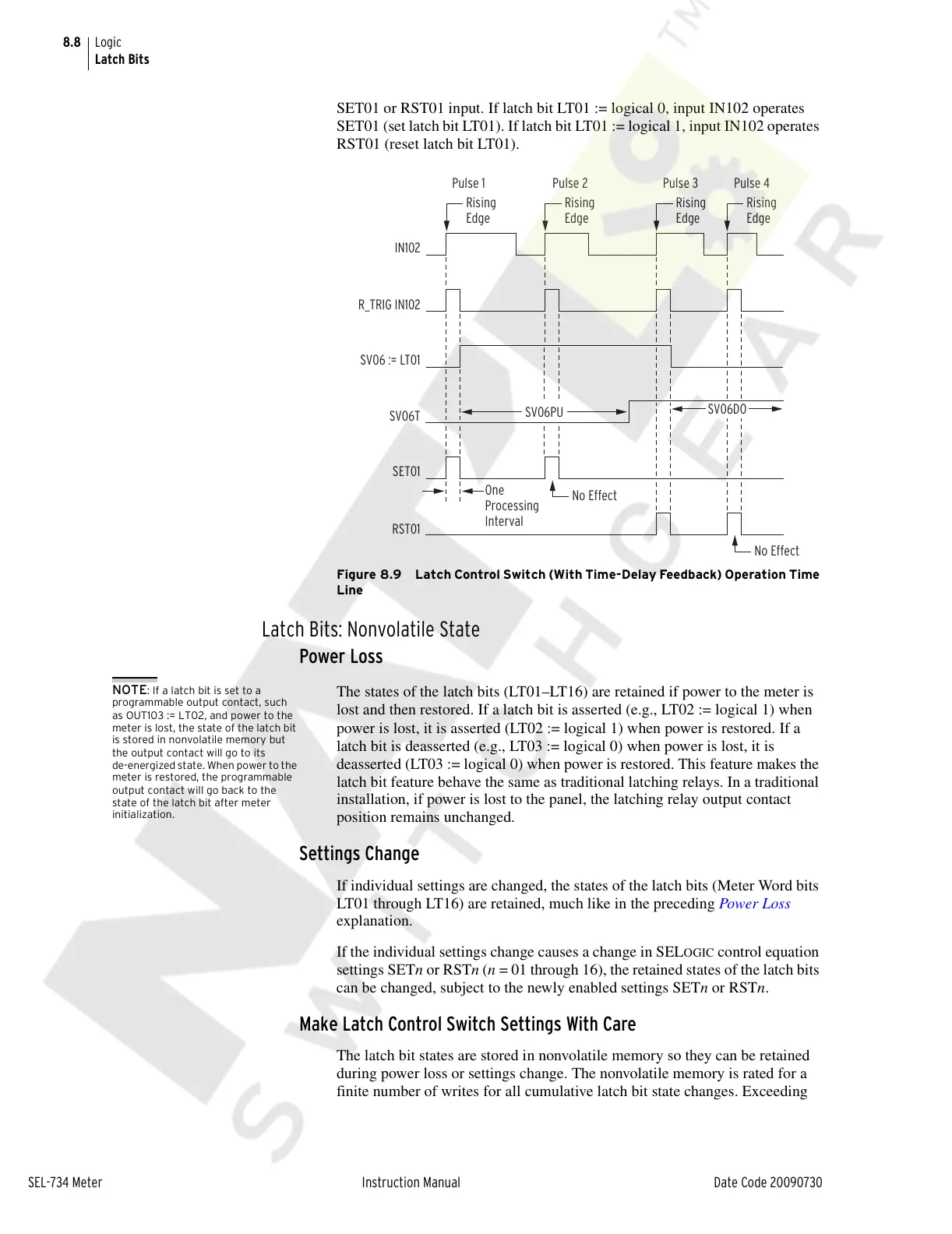
SET01 or RST01 input. If latch bit LT01 := logical 0, input IN102 operates
SET01 (set latch bit LT01). If latch bit LT01 := logical 1, input IN102 operates
RST01 (reset latch bit LT01).
Figure 8.9 Latch Control Switch (With Time-Delay Feedback) Operation Time
Line
Latch Bits: Nonvolatile State
Power Loss
NOTE: If a latch bit is set to a
programmable output contact, such
as OUT103 := LT02, and power to the
meter is lost, the state of the latch bit
is stored in nonvolatile memory but
the output contact will go to its
de-energized state. When power to the
meter is restored, the programmable
output contact will go back to the
state of the latch bit after meter
initialization.
The states of the latch bits (LT01–LT16) are retained if power to the meter is
lost and then restored. If a latch bit is asserted (e.g., LT02 := logical 1) when
power is lost, it is asserted (LT02 := logical 1) when power is restored. If a
latch bit is deasserted (e.g., LT03 := logical 0) when power is lost, it is
deasserted (LT03 := logical 0) when power is restored. This feature makes the
latch bit feature behave the same as traditional latching relays. In a traditional
installation, if power is lost to the panel, the latching relay output contact
position remains unchanged.
Settings Change
If individual settings are changed, the states of the latch bits (Meter Word bits
LT01 through LT16) are retained, much like in the preceding Power Loss
explanation.
If the individual settings change causes a change in SEL
OGIC control equation
settings SETn or RSTn (n = 01 through 16), the retained states of the latch bits
can be changed, subject to the newly enabled settings SETn or RSTn.
Make Latch Control Switch Settings With Care
The latch bit states are stored in nonvolatile memory so they can be retained
during power loss or settings change. The nonvolatile memory is rated for a
finite number of writes for all cumulative latch bit state changes. Exceeding
RST01
R_TRIG IN102
IN102
SET01
Rising
Edge
One
Processing
Interval
SV06DO
SV06PU
Pulse 1 Pulse 2 Pulse 3 Pulse 4
Rising
Edge
Rising
Edge
No Effect
No Effect
Rising
Edge
SV06 := LT01
SV06T
Courtesy of NationalSwitchgear.com