4.25
Date Code 20090730 Instruction Manual SEL-734 Meter
Metering
Transformer/Line Loss Compensation
are known, the per-phase losses can be calculated. In a three-phase system, the
SEL-734 assumes that each conductor has identical impedances and solely
series losses are considered.
The SEL-734 uses the following equations to calculate line-loss compensation
values.
Supply line loss:
Equation 4.16
Equation 4.17
Equation 4.18
Equation 4.19
Load line losses are calculated similarly by substituting the supply line
settings with the load line settings (i.e., SPnL is calculated similarly to LPnL,
the load-line real power per-phase loss).
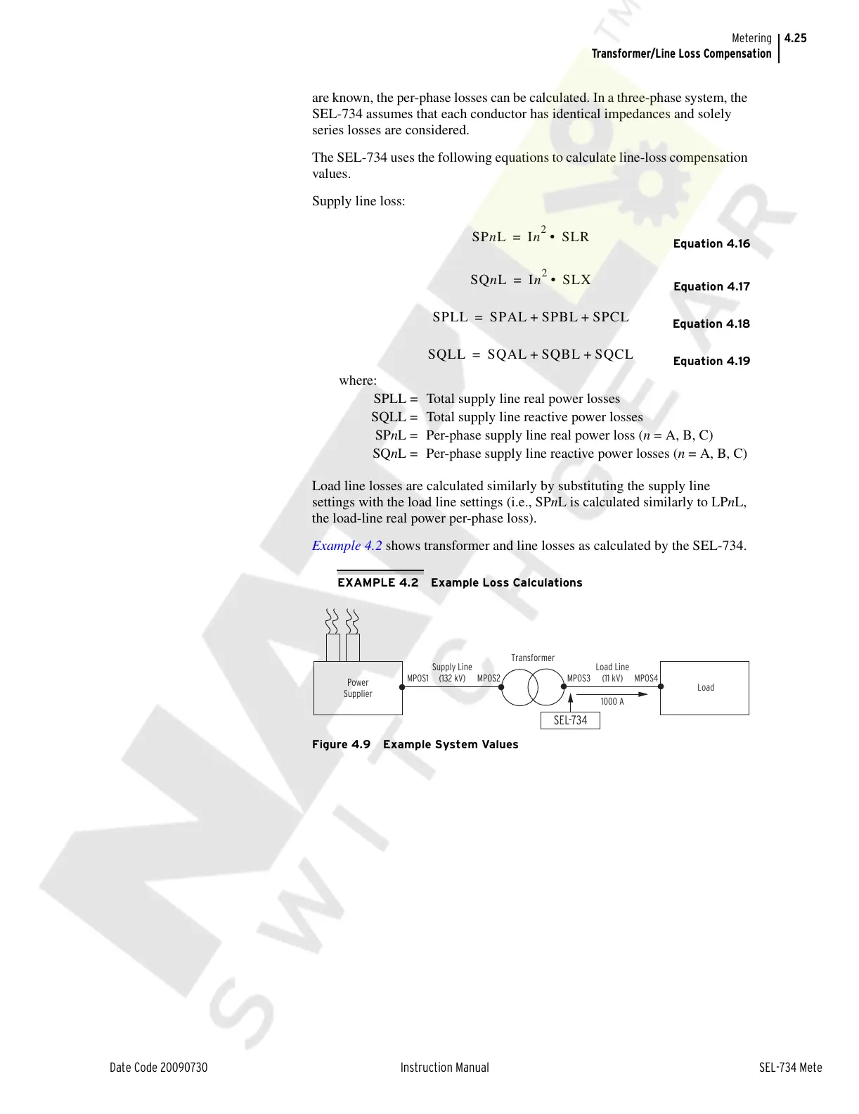
Example 4.2 shows transformer and line losses as calculated by the SEL-734.
EXAMPLE 4.2 Example Loss Calculations
Figure 4.9 Example System Values
where:
SPLL = Total supply line real power losses
SQLL = Total supply line reactive power losses
SPnL = Per-phase supply line real power loss (n = A, B, C)
SQnL = Per-phase supply line reactive power losses (n = A, B, C)
Transformer
Load Line
(11 kV)
1000 A
Supply Line
(132 kV)MPOS1 MPOS2 MPOS4MPOS3
Load
Power
Supplier
SEL-734
Courtesy of NationalSwitchgear.com