4.24
SEL-734 Meter Instruction Manual Date Code 20090730
Metering
Transformer/Line Loss Compensation
Transformer Losses Three-phase transformer loss calculations are shown in
Equation 4.6–Equation 4.15. For three single-phase transformer applications,
%Z, %IMAG, LWCU, and LWFE must be averaged.
The designator “B” will follow all primary (user-defined) values to distinguish
them from secondary (internal metered) values.
Equation 4.6
Equation 4.7
Equation 4.8
Equation 4.9
Where:
Equation 4.10
Equation 4.11
Equation 4.12
Equation 4.13
Equation 4.14
Equation 4.15
LVCU = copper (load) VAR loss, at rated current
LVFE = iron (no-load) VAR loss, at rated voltage
Line Losses The impedance of power carrying conductors causes line losses. The resistive
component causes active power losses (watts) while the reactive component
causes reactive power (VAR) losses. If the conductor resistance and reactance
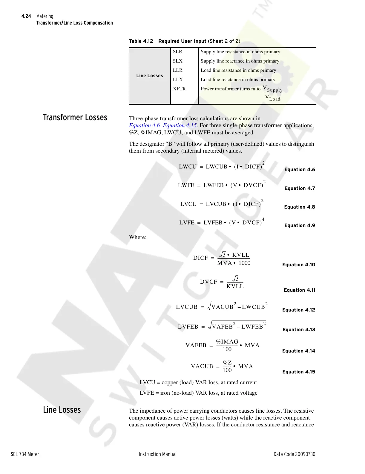
Line Losses
SLR Supply line resistance in ohms primary
SLX Supply line reactance in ohms primary
LLR Load line resistance in ohms primary
LLX Load line reactance in ohms primary
XFTR Power transformer turns ratio
Table 4.12 Required User Input (Sheet 2 of 2)
V
Supply
V
Load
--------------------
LWCU LWCUB I DICF• ()
2
• =
LWFE LWFEB V DVCF• ()
2
• =
LVCU LVCUB I DICF• ()
2
• =
LVFE LVFEB V DVCF• ()
4
• =
DICF
3 KVLL•
MVA 1000•
---------------------------------=
DVCF
3
KVLL
-----------------=
VAFEB
%IMAG
100
----------------------
MVA• =
VACUB
%Z
100
---------
MVA• =
Courtesy of NationalSwitchgear.com