2.14
SEL-734 Meter Instruction Manual Date Code 20090730
Installation
Circuit Board Connections
Cleaning
Use care when cleaning the SEL-734. Use a mild soap or detergent solution
and a damp cloth to clean the chassis. Do not use abrasive materials, polishing
compounds, or harsh chemical solvents (such as xylene or acetone) on any
surface.
Circuit Board Connections
Accessing the
Meter Circuit Boards
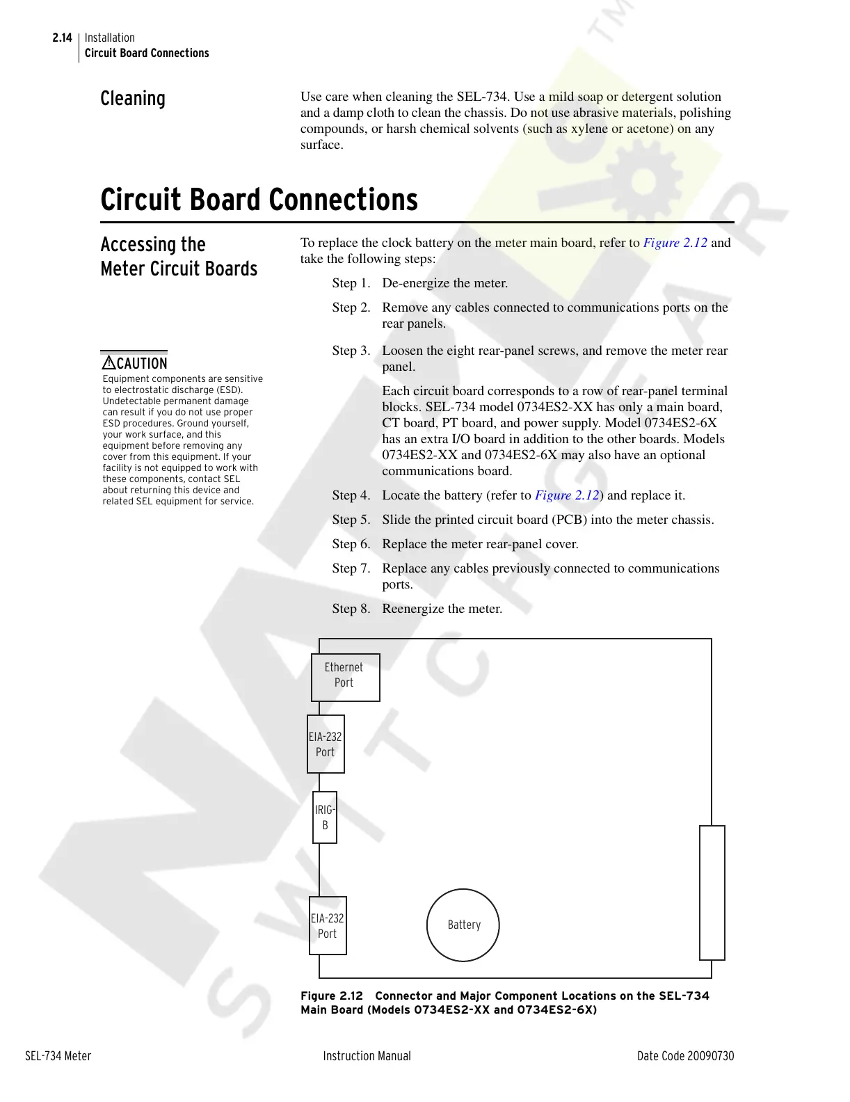
To replace the clock battery on the meter main board, refer to Figure 2.12 and
take the following steps:
Step 1. De-energize the meter.
Step 2. Remove any cables connected to communications ports on the
rear panels.
Equipment components are sensitive
to electrostatic discharge (ESD).
Undetectable permanent damage
can result if you do not use proper
ESD procedures. Ground yourself,
your work surface, and this
equipment before removing any
cover from this equipment. If your
facility is not equipped to work with
these components, contact SEL
about returning this device and
related SEL equipment for service.
!
CAUTION
Step 3. Loosen the eight rear-panel screws, and remove the meter rear
panel.
Each circuit board corresponds to a row of rear-panel terminal
blocks. SEL-734 model 0734ES2-XX has only a main board,
CT board, PT board, and power supply. Model 0734ES2-6X
has an extra I/O board in addition to the other boards. Models
0734ES2-XX and 0734ES2-6X may also have an optional
communications board.
Step 4. Locate the battery (refer to Figure 2.12) and replace it.
Step 5. Slide the printed circuit board (PCB) into the meter chassis.
Step 6. Replace the meter rear-panel cover.
Step 7. Replace any cables previously connected to communications
ports.
Step 8. Reenergize the meter.
Figure 2.12 Connector and Major Component Locations on the SEL-734
Main Board (Models 0734ES2-XX and 0734ES2-6X)
Ethernet
Port
IRIG-
B
EIA-232
Port
EIA-232
Port
Battery
Courtesy of NationalSwitchgear.com