4.4
SEL-734 Meter Instruction Manual Date Code 20090730
Metering
Instantaneous Metering
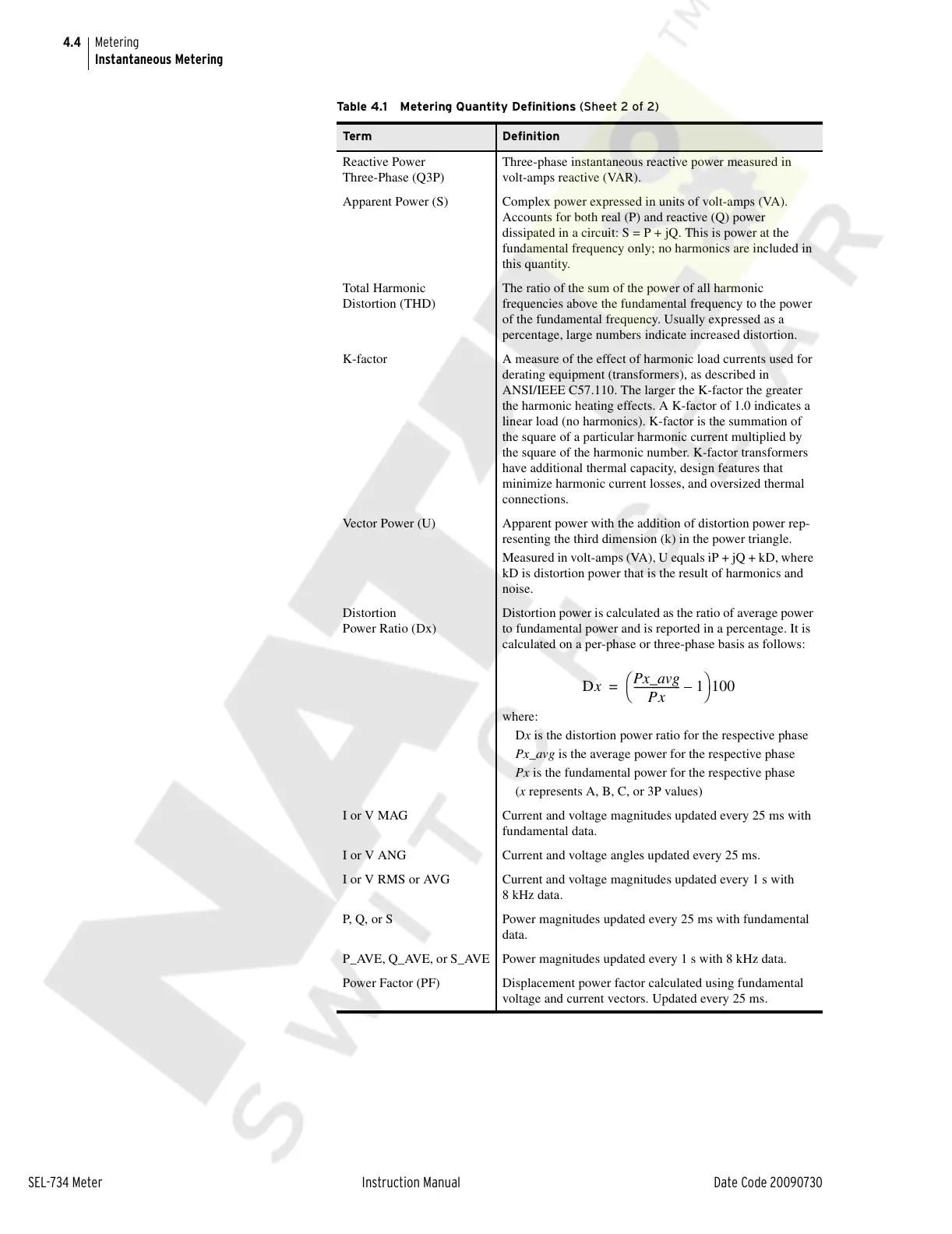
Reactive Power
Three-Phase (Q3P)
Three-phase instantaneous reactive power measured in
volt-amps reactive (VAR).
Apparent Power (S) Complex power expressed in units of volt-amps (VA).
Accounts for both real (P) and reactive (Q) power
dissipated in a circuit: S = P + jQ. This is power at the
fundamental frequency only; no harmonics are included in
this quantity.
Total Harmonic
Distortion (THD)
The ratio of the sum of the power of all harmonic
frequencies above the fundamental frequency to the power
of the fundamental frequency. Usually expressed as a
percentage, large numbers indicate increased distortion.
K-factor A measure of the effect of harmonic load currents used for
derating equipment (transformers), as described in
ANSI/IEEE C57.110. The larger the K-factor the greater
the harmonic heating effects. A K-factor of 1.0 indicates a
linear load (no harmonics). K-factor is the summation of
the square of a particular harmonic current multiplied by
the square of the harmonic number. K-factor transformers
have additional thermal capacity, design features that
minimize harmonic current losses, and oversized thermal
connections.
Vector Power (U) Apparent power with the addition of distortion power rep-
resenting the third dimension (k) in the power triangle.
Measured in volt-amps (VA), U equals iP + jQ + kD, where
kD is distortion power that is the result of harmonics and
noise.
Distortion
Power Ratio (Dx)
Distortion power is calculated as the ratio of average power
to fundamental power and is reported in a percentage. It is
calculated on a per-phase or three-phase basis as follows:
where:
Dx is the distortion power ratio for the respective phase
Px_avg is the average power for the respective phase
Px is the fundamental power for the respective phase
(x represents A, B, C, or 3P values)
I or V MAG Current and voltage magnitudes updated every 25 ms with
fundamental data.
I or V ANG Current and voltage angles updated every 25 ms.
I or V RMS or AVG Current and voltage magnitudes updated every 1 s with
8 kHz data.
P, Q, or S Power magnitudes updated every 25 ms with fundamental
data.
P_AVE, Q_AVE, or S_AVE Power magnitudes updated every 1 s with 8 kHz data.
Power Factor (PF) Displacement power factor calculated using fundamental
voltage and current vectors. Updated every 25 ms.
Table 4.1 Metering Quantity Definitions (Sheet 2 of 2)
Ter m Definition
Dx
Px_avg
Px
------------------1–
⎝⎠
⎛⎞
100=
Courtesy of NationalSwitchgear.com