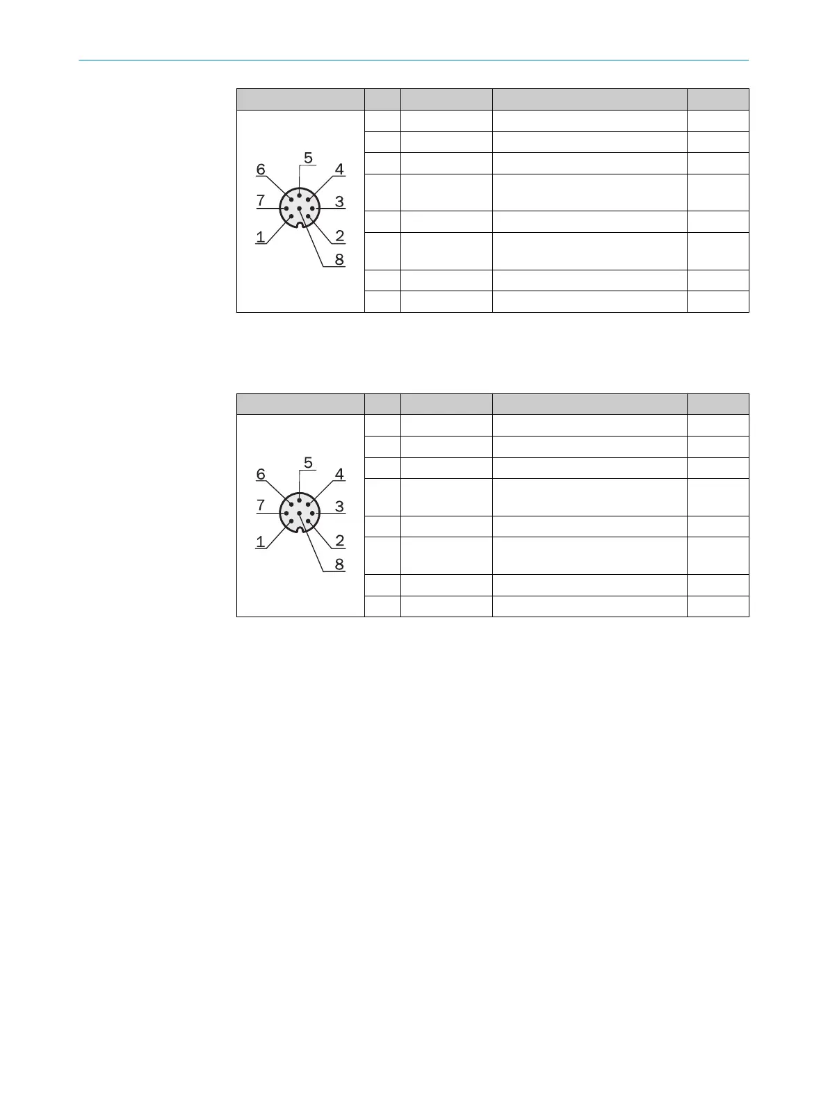
Male connector Pin Signal Meaning Color
1 L+ 24 V supply voltage Brown
2 Sync_A Synchronization White
3 M GND supply voltage Blue
4 Q1/C Switching output 1 with
IO-Link interface
Black
5 Sync_B Synchronization Gray
6 Q2/IN1 Switching output 2 or
Switching input 1
1
Pink
7 QA1 Analog output 1 Violet
8 QA2 Analog output 2 Orange
Table 27: Pin assignment, I/O, MLG2 Pro receiver, with QA
1
Configurable
Receiver I/O connection with RS485 interface: M12/8-pin, Acoded
Male connector Pin Signal Meaning Color
1 L+ 24 V supply voltage Brown
2 Sync_A Synchronization White
3 M GND supply voltage Blue
4 Q1/C Switching output 1 with
IO-Link interface
Black
5 Sync_B Synchronization Gray
6 Q2/IN1 Switching output 2 or
Switching input 1
1
Pink
7 RS485_A RS-485 interface Violet
8 RS485_B RS485 interface Orange
Table 28: Pin assignment, I/O, MLG2 Pro receiver, with RS-485
1
Configurable
ELECTRICAL INSTALLATION 5
8017460.ZIK1/2017-02-13 | SICK O P E R A T I N G I N S T R U C T I O N S | MLG-2 Pro
45
Subject to change without notice