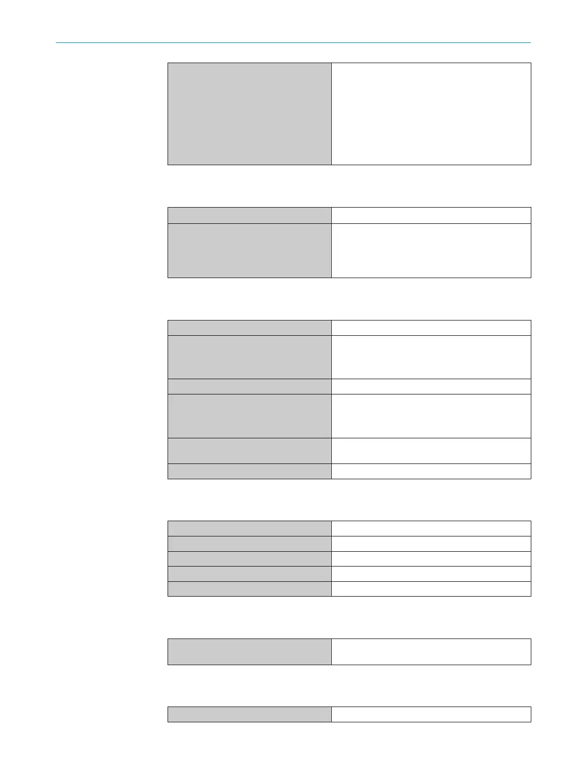
Required overvoltage protection when
using the following wire gages
•
AWG 20/0.52 mm
2
•
AWG 22/0.32 mm
2
•
AWG 24/0.20 mm
2
•
AWG 26/0.13 mm
2
•
AWG 28/0.08 mm
2
•
AWG 30/0.05 mm
2
•
5 A
•
3 A
•
2 A
•
1 A
•
0.8 A
•
0.5 A
Table 44: MLG-2 data sheet - electrical specifications
Inputs
Input voltage 0 V … V
S
Logic level switching points
•
HIGH
•
LOW
•
> 15 V
•
< 5 V
The pulse duration must be greater than the
response time (see figure 129, page 122)
Table 45: MLG-2 data sheet - inputs
Outputs
Switching type Push-pull
Logic level switching points
•
HIGH
•
LOW
•
V
S
– 3 V
•
< 3 V
Maximum output current per output 100 mA
Output load per output
•
Capacitive
•
Inductive
•
100 nF
•
1 H
Load resistance for analog output 4 …
20 mA
< 600 W
Response time see figure 129, page 122
Table 46: MLG-2 data sheet - outputs
Ethernet interface
Data transmission rate 100 Mbit/s
Default IP address 192.168.200.100
Subnet mask 255.255.255.000
Protocol TCP/IP
Maximum length of cable According to IEE802.3 (typ. 100 m)
Table 47: MLG-2 data sheet - Ethernet interface
RS-485 interface
Data transmission rate
1200, 2400, 4800, 9600, 19200, 38400, 57600,
115200, 230400, 460800, 921600 bit/s
Table 48: MLG-2 data sheet - RS-485 interface
IO-Link interface
Version
1.1
Table 49: MLG-2 data sheet - IO-Link interface
13 TECHNICAL DATA
120
O P E R A T I N G I N S T R U C T I O N S | MLG-2 Pro 8017460.ZIK1/2017-02-13 | SICK
Subject to change without notice