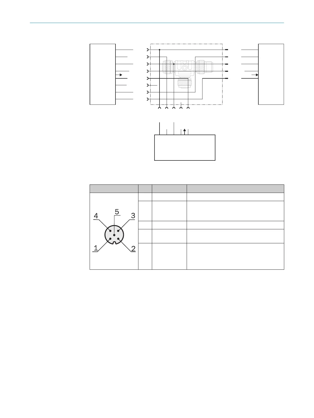
Sender, receiver, IO-Link master connection
Receiver
Sender
T-Junction, 5-pin
L+
1
M
2
brn
wht
blk
blu
gra
pnk
vio
ora
IO-Link
Master
L+
Sync_A
M
Sync_B
1
2
3
5
1
2
4
3
5
Q1/C
4
Q2/IN1
6
1
7
2
8
1 2 3 5
Sync_B
4
Test_In
M
L+
Sync_A
1 Q3/QA1/RS-485_A
2 Q4/IN2/QA2/RS-485_B
Q1/C
Figure 38: T-distributor for sender, receiver, IO-Link master
Male connector Pin Signal Meaning
1 L+ 24 V supply voltage
2 Q3
QA1
RS485_A
Switching output 3 or
Analog output 1 or
RS-485 interface
3 M GND supply voltage
4 Q1/C Switching output 1 with
IO-Link interface
5 Q4
IN2
QA2
RS485_B
Switching output 4 or
Switching input 2 or
Analog output 2 or
RS-485 interface
Table 30: Pin assignment of the IO-Link master connection
5 ELECTRICAL INSTALLATION
48
O P E R A T I N G I N S T R U C T I O N S | MLG-2 Pro 8017460.ZIK1/2017-02-13 | SICK
Subject to change without notice