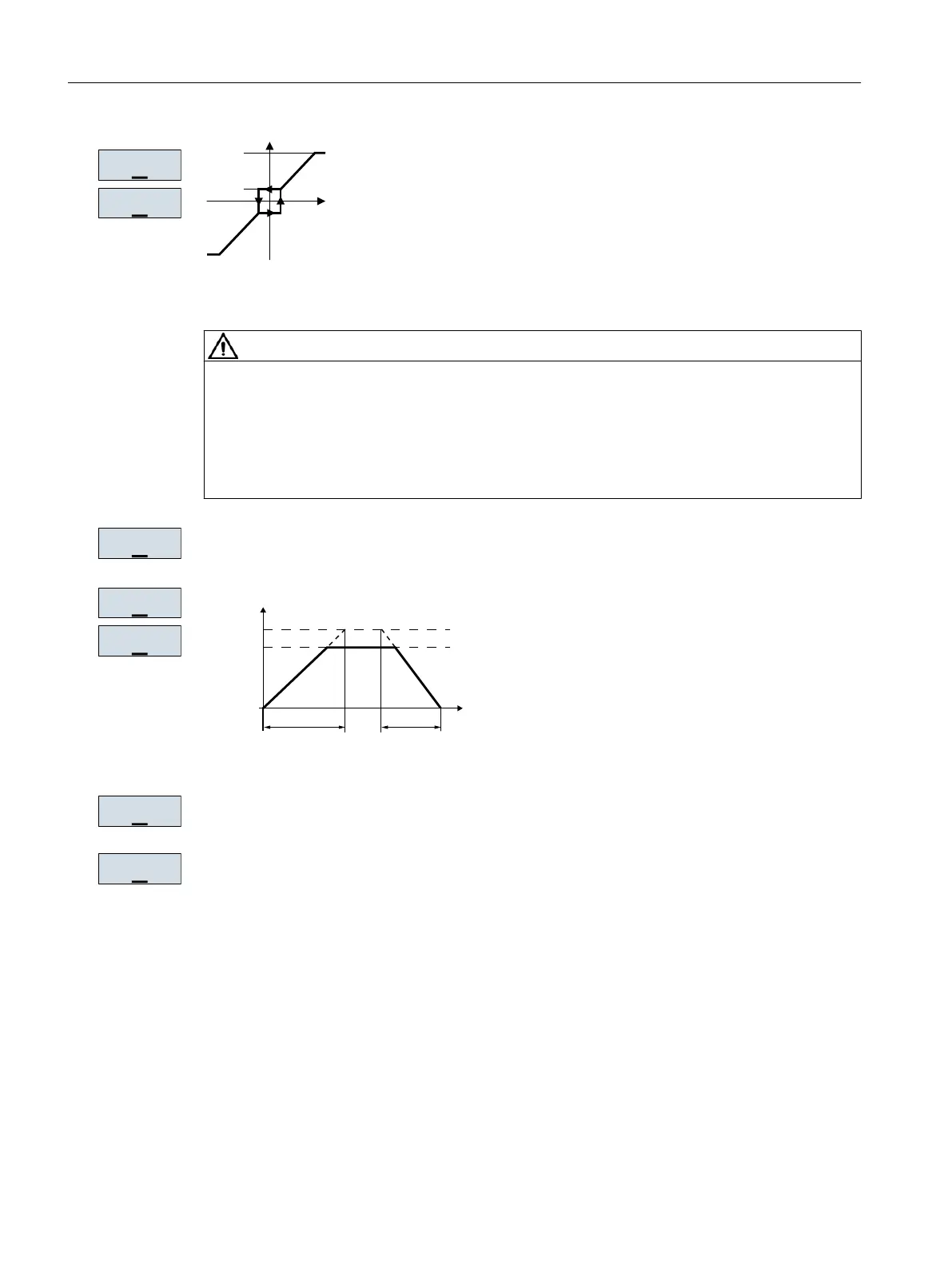
Figure 5-13 Minimum and maximum motor frequency
CAUTION
Material damage caused by unexpected acceleration of the motor
Depending on the Power Module, the inverter sets the minimum frequency p1080 to 20% of
the maximum frequency. Also for a setpoint = 0, for p1080 > 0, after the motor is switched
on it accelerates to the minimum frequency. An unexpected acceleration of the motor can
cause material damage.
● If the application requires a minimum frequency = 0, then set p1080 = 0.
Scaling of analog input 0
I
6HWSRLQW
3
3
W
I
PD[
3
Figure 5-14 Ramp-up and ramp-down time of the motor
Ramp-down time for the OFF3 command
Motor data identification: Select the method which the inverter uses to measure the data of
the connected motor:
● OFF: Motor data is not measured.
● STIL ROT: Recommended setting: Measure the motor data at standstill and with the motor
rotating. The inverter switches off the motor after the motor data identification has been
completed.
3
5$0383
3
5$03':1
Commissioning
5.4 Quick commissioning using the BOP-2 operator panel
Converter with the CU230P-2 Control Units
170 Operating Instructions, 09/2017, FW V4.7 SP9, A5E34257946B AE

 Loading...


