Technical Specifications
7-58
ET 200X Distributed I/O Device
EWA 4NEB 780601602-06
Pinout of the sockets for DO
The following table shows the pinout of the four sockets used to connect the digital
outputs. You can find the layout of the sockets in Appendix C. The connector wiring
is described in Section 4.4.4.
Table 7-27 Pinout of the sockets for 4-channel digital outputs
Pin Assignment of
socket X1
Assignment of
socket X2
Assignment of
socket X3
Assignment of
socket X4
Front view
of socket
(Front)
1 –
2 Output signal,
channel 1*
– Output signal,
channel 3*
–
2
3 Chassis ground, load power supply
1
2
3
5
4 Output signal,
channel 0
Output signal,
channel 1*
Output signal,
channel 2
Output signal,
channel 3*
4
5 PE
* Note: Channel 1 and channel 3 are only allowed to be used at one socket (X1/X2 or X3/X4).
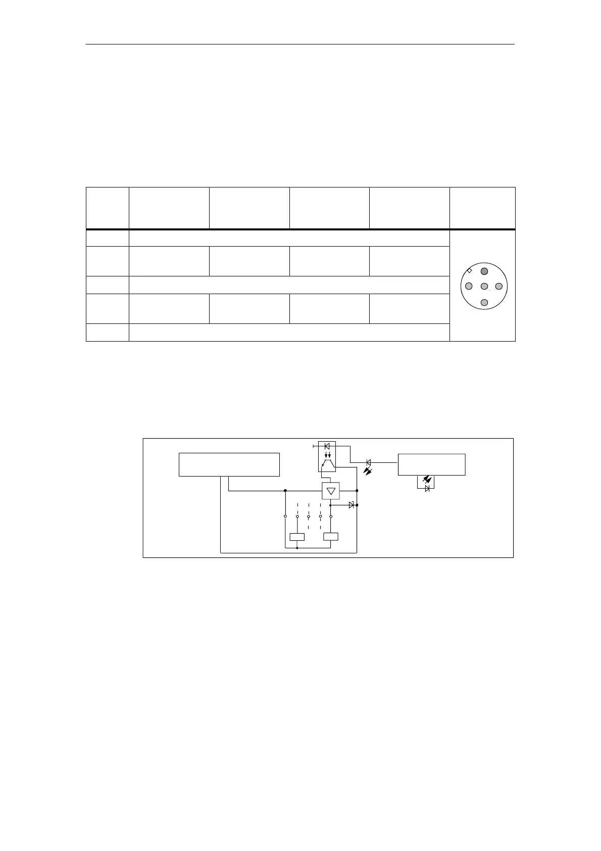
Basic circuit diagram
The basic circuit diagram of the expansion module is shown below.
Socket con-
nections (see
Table 7-27)
Backplane bus
interface
2M
2L+
2M
Load power supply via
backplane bus
SF
Figure 7-14 Basic circuit diagram of expansion module EM 142 DO 4 x DC 24V/2A
Covering up unused connections
You must seal off any connections which are not required with M12 screw caps, in
order to ensure that the degree of protection (IP 65, IP 66 or IP 67) is achieved.
 Loading...


