6 Pro
rammin
the control
6
03/2006
6.9 Axes and spindles
6-79
© Siemens AG 2006 All Rights Reserved
SINUMERIK 840D/810D Start-Up Guide (IADC) – 03/2006 Edition
MD 10000: AXCONF_MACHAX_NAME_TAB
Here, an axis name is defined in
MD 10000: AXCONF_MACHAX_NAME_TAB for each machine axis.
Example:
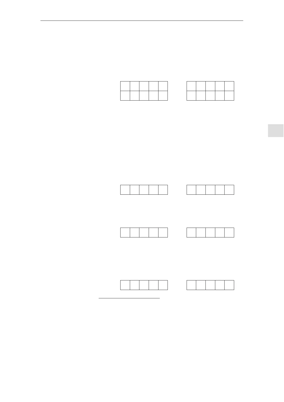
Lathe Milling machine
with X, Z, C axis/spindle 4 axes+spindles/C axis
X1
01
Z1 C1
342
X1
01
Y1 Z1
342
A1 C1
MD 10000
Index
Example for a milling machine: MD10000
AXCONF_MACHAX_NAME_TAB[0] = X1
AXCONF_MACHAX_NAME_TAB[1] = Y1
AXCONF_MACHAX_NAME_TAB[2] = Z1
AXCONF_MACHAX_NAME_TAB[3] = A1
AXCONF_MACHAX_NAME_TAB[4] = C1
S MD 20070: AXCONF_MACHAX_USED[0...7]
The channel-specific MDs are used to assign the machine axes to
a geometry channel.
Lathe Milling machine
1234512300
S MD 20080: AXCONF_CHANAX_NAME_TAB[0...7]
The MD defines the names of the axes on the channel. Enter the names of
the geometry and additional axes here.
ACCXZ ZXY
S MD 20060: AXCONF_GEOAX_NAME_TAB[0...2]
The MD defines the names that are used in the part programs for the geo-
metry axes (machine-independent workpiece axes).
XYZXY*Z
* For a transformation e.g. TRANSMIT
the 2nd geometry coordinates must also
be given a name (e.g. “Y”)
S MD 20050: AXCONF_GEOAX_ASSIGN_TAB[0...2]
Defines the allocation of geometry axes to the axes of the channel
(MD20070) without transformation. For allocation while transformation is
active, see:
1. Machine level
2. Channel level
3. Program level

 Loading...


