6 Pro
rammin
the control
6
03/2006
6.9 Axes and spindles
6-80
© Siemens AG 2006 All Rights Reserved
SINUMERIK 840D/810D Start-Up Guide (IADC) – 03/2006 Edition
Reference material: /FB1/ K2, Functional description of the basic machines,
Axes, coordinate systems, frames
Note the relationship with the inclusion of tool offsets in the calculation (G17,
G18, G19).
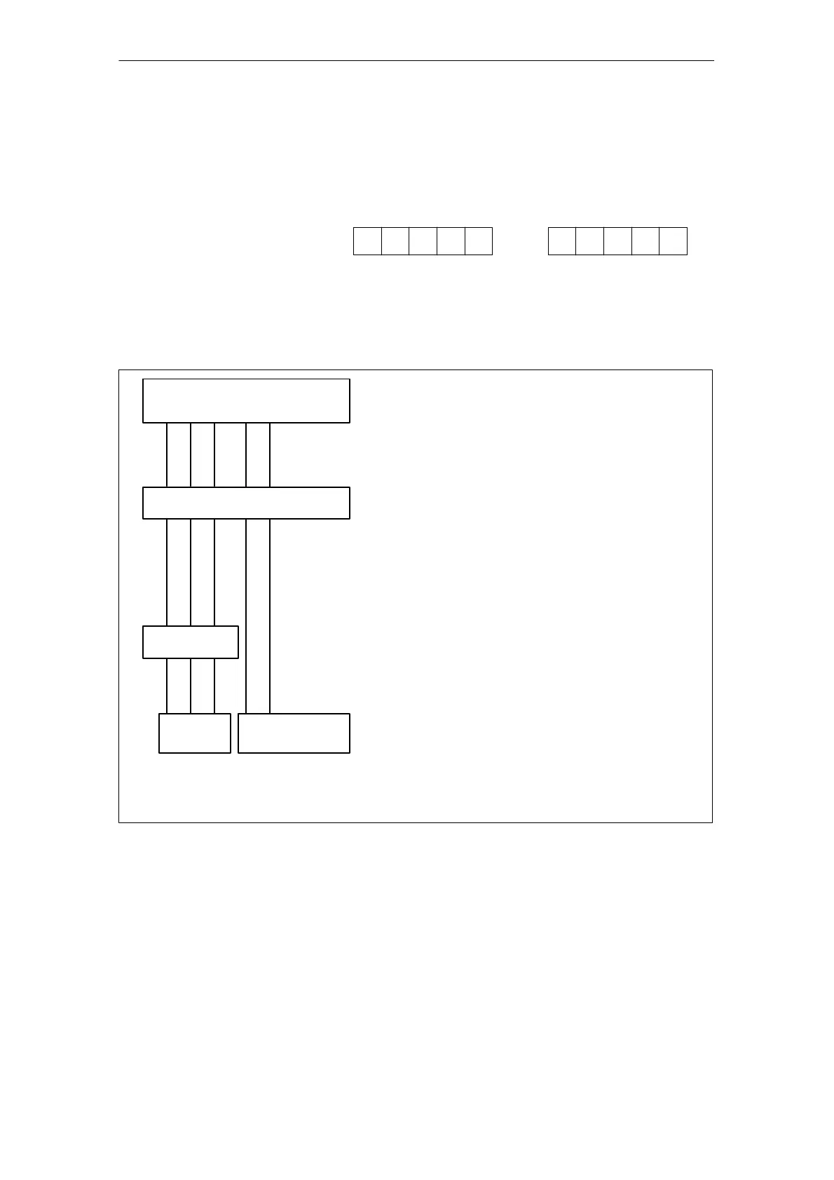
123102
During program execution, the coordinates that are not assigned via
MD 20060/MD 20050 are always mapped directly onto the axes of the channel
(in the milling machine example below, axes A and C).
Machine axis no. for channel
1 2 3 4 5
A C
Axis name on the channel (special axes)
X Y Z
GEO axis
Assignment of
GEO axes
A C
Special axes
MD 20070: AXCONF_MACHAX_USED
Machine axes used on the channel
AXCONF_MACHAX_USED[0]=1
AXCONF_MACHAX_USED[1]=2
AXCONF_MACHAX_USED[2]=3
AXCONF_MACHAX_USED[3]=4
AXCONF_MACHAX_USED[4]=5
MD 20080: AXCONF_CHANAX_NAME_TAB
Names of the special axes on the channel (for use in
the part program)
AXCONF_CHANAX_NAME_TAB [0]=
AXCONF_CHANAX_NAME_TAB [1]=
AXCONF_CHANAX_NAME_TAB [2]=
AXCONF_CHANAX_NAME_TAB [3]=A
AXCONF_CHANAX_NAME_TAB [4]=C
MD 20050: AXCONF_GEOAX_ASSIGN_TAB
Allocation of GEOaxis to axes on the channel.
AXCONF_GEOAX_ASSIGN_TAB [0]=1
AXCONF_GEOAX_ASSIGN_TAB [1]=2
AXCONF_GEOAX_ASSIGN_TAB [2]=3
X to X, Y to Y, Z to Z
Names of the GEO axes
MD 20060: AXCONF_GEO_AX_NAME_TAB[0]=X
MD 20060: AXCONF_GEO_AX_NAME_TAB[0]=Y
MD 20060: AXCONF_GEO_AX_NAME_TAB[0]=Z
Fig. 6-3 Example of milling machine: 4 axes + spindle/C axis

 Loading...


