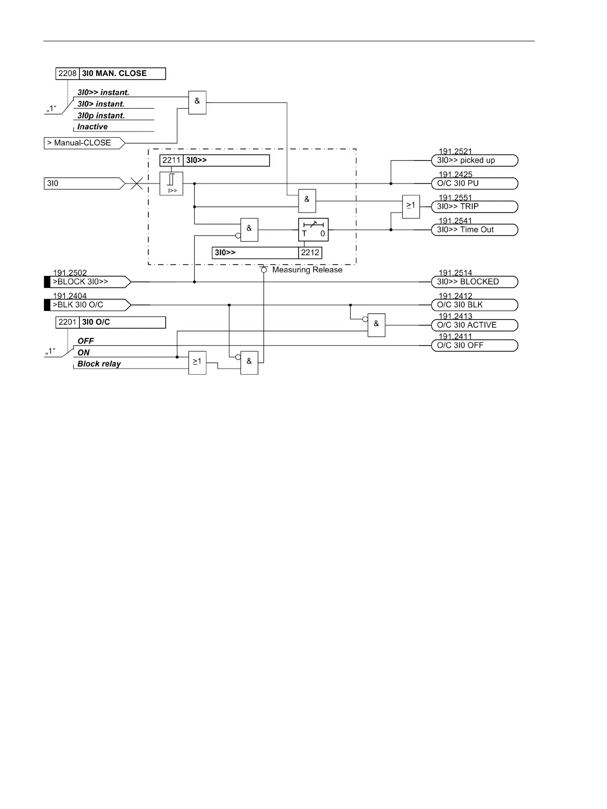
[logik-hochstromstufen-i-fuer-nullstrom, 1, en_GB]
Figure 2-68
Logic diagram of the high-set stages I>> for residual current (simplified)
Each phase current and the zero sequence current 3·Ι
0
are, additionally, compared with the setting value I>
(common setting for the three phase currents) and 3I0> (independent setting for 3Ι
0
). If inrush restraint is
used, a frequency analysis is performed first. Depending on the detection of inrush currents, either normal
pickup annunciations or relevant inrush messages are issued. After user-configured delay times T I> or T
3I0> have elapsed, a trip signal is issued assuming that no inrush current is detected or inrush restraint is
disabled. If inrush restraint is enabled and inrush current is detected, there will be no tripping. Nevertheless,
an annunciation is generated indicating that the time expired. Tripping signals and signals on the expiration of
time delay are available separately for each stage. The reset values are approximately 95 % below the pickup
value for settings above Ι
N
. Lower values require a higher hysteresis in order to avoid intermittent pickup on
currents near the pickup value (e.g. 20 % at 0.2 · Ι
N
).
Figure 2-69 and Figure 2-70 show the logic diagrams for the overcurrent stages I> for phase currents and for
the zero sequence current stage 3I0>.
Functions
2.4 Time Overcurrent Protection for Phase and Residual Currents
138 SIPROTEC 4, 7UT6x, Manual
C53000-G1176-C230-5, Edition 09.2016

 Loading...


